
SM6S Series
Vishay Semiconductors
formerly General Semiconductor
Document Number 88384
www.vishay.com
01-Aug-02
1
New Product
Surface Mount Automotive Transient Voltage Suppressors
Stand-off Voltage 10 to 36V
Peak Pulse Power 4600W (10/1000
µ
s)
3600W (10/10,000
µ
s)
Patented*
Maximum Ratings and Thermal Characteristics
(T
C
= 25°C unless otherwise noted)
Parameter
Symbol
Value
Unit
Peak pulse power dissipation with 10/1000
µ
s waveform
4600
10/10,000
µ
s waveform
P
PPM
3600
W
Steady state power dissipation
P
D
6.0
W
Peak pulse current with a 10/1000
µ
s waveform
(NOTE 1)
I
PPM
See Table 1
A
Peak forward surge current, 8.3ms single half sine-wave
I
FSM
600
A
Typical thermal resistance junction to case
R
JC
0.95
°C/W
Operating junction and storage temperature range
T
J
, T
STG
55 to +175
°C
Notes: (1) Non-repetitive current pulse derated above T
A
=25°C
0.093(2.4)
0.116(3.0)
0.059(1.5)
0.098(2.5)
0.098(2.5)
0.138(3.5)
0.366(9.3)
0.343(8.7)
0.406(10.3)
0.382(9.7)
0.342(8.7)
0.327(8.3)
0.413(10.5)
0.374(9.5)
0.539(13.7)
0.524(13.3)
LEAD 2/METAL HEATSINK
0.020(0.5)
0.028(0.7)
0.016 (0.4) Min.
0.197(5.0)
0.185(4.7)
LEAD 1
0.628(16.0)
0.592(15.0)
*
Patent #'s:
4,980,315
5,166,769
5,278,095
Features
· Ideally suited for load dump protection
· Plastic package has Underwriters Laboratory
Flammability Classification 94V-0
· High temperature stability due to unique oxide passiva-
tion and patented PAR
®
construction
· Integrally molded heatsink provides a very low thermal
resistance for maximum heat dissipation
· Low leakage current at T
J
= 175°C
· High temperature soldering guaranteed:
260°C for 10 seconds at terminals
· Meets ISO7637-2 surge spec.
· Low forward voltage drop
0.413(10.5)
0.374(9.5)
0.366(9.3)
0.343(8.7)
0.606(15.4)
0.583(14.8)
0.150(3.8)
0.126(3.2)
0.091(2.3)
0.067(1.7)
0.116(3.0)
0.093(2.4)
Mounting Pad Layout
Mechanical Data
Case: Molded plastic body, surface mount with heatsink
integrally mounted in the encapsulation
Terminals: Plated, solderable per MIL-STD-750, Method 2026
Polarity: Heatsink is anode
Mounting Position: Any
Weight: 0.091 oz., 2.58 g
Packaging codes/options:
2D/750 per 13" Reel (16mm Tape),
anode towards sprocket hole, 4.5K/box
2E/750 per 13" Reel (16mm Tape),
cathode towards sprocket hole, 4.5K/box
DO-218AB
Dimensions in
inches and (millimeters)
SM6S Series
Vishay Semiconductors
formerly General Semiconductor
Document Number 88384
www.vishay.com
01-Aug-02
3
Ratings and
Characteristic Curves
(T
A
= 25°C unless otherwise noted)
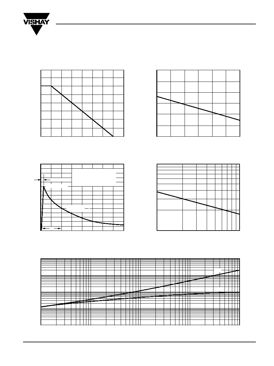
Power Derating Curve
0
2.0
4.0
6.0
8.0
0
50
100
150
200
P
o
w
er Dissipation (W)
Re
v
erse Surge P
o
w
er (W)
Pulse Width (ms) 1/2 I
PP
Exponential Waveform
1,000
10,000
10
100
Case Temperature (
°
C)
0
50
100
150
0
10
20
30
40
Input P
eak Pulse Current %
Time, ms (t)
Pulse Waveform
Reverse Power Capability
T
A
= 25
°
C
Pulse width (t
d
) is defined as
the point where the peak
current decays to 50% of I
PP
t
d
t
r
= 10
µ
s
Peak Value I
PP
Half Value
I
PP
2
Load Dump Power Characteristics
(10ms Exponential Waveform)
0
2,000
1,000
3,000
4,000
5,000
6,000
25
50
75
100
125
150
175
Load Dump P
o
w
er (W)
Case Temperature (
°
C)
T
r
ansient
Ther
mal Impedance (
°
C/W)
0.01
1
10
100
10
1
100
0.01
0.1
t Pulse Width (sec.)
0.1
R
JA
R
JC
Typical Transient Thermal Impedance
