Peak Pulse Power 400W
Stand-off Voltage 5.8 to 376V
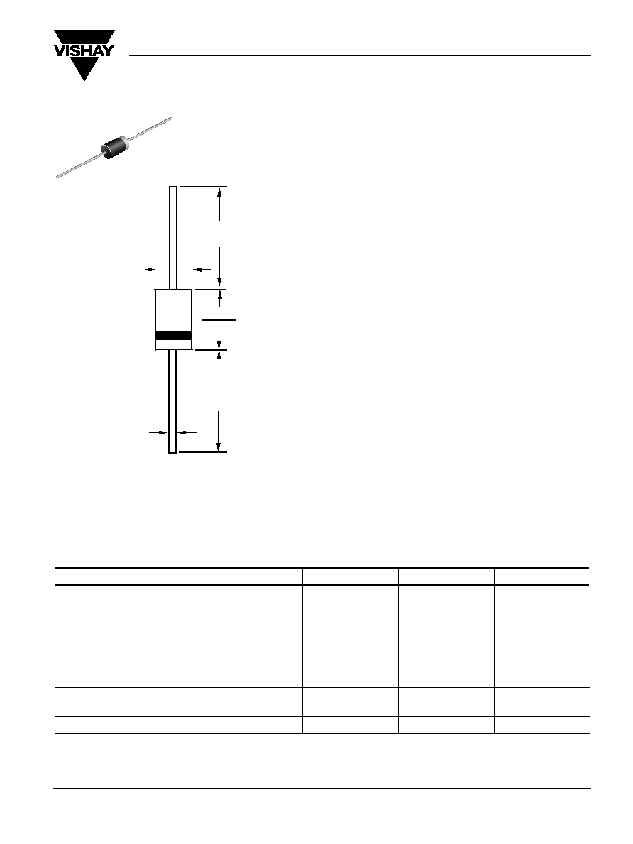
0.107 (2.7)
0.080 (2.0)
0.034 (0.86)
0.028 (0.71)
DIA.
1.0 (25.4)
MIN.
1.0 (25.4)
MIN.
0.205 (5.2)
0.160 (4.1)
DIA.
Dimensions in inches and (millimeters)
DO-204AL (DO-41 Plastic)
Maximum Ratings and Thermal Characteristics
(T
A
= 25°C unless otherwise noted)
Parameter
Symbol
Limit
Unit
Peak pulse power dissipation with a 10/1000
µ
s waveform
P
PPM
Minimum 400
W
(Note 1, Fig. 1)
Peak pulse current with a 10/1000
µ
s waveform
(Note 1)
I
PPM
See Next Table
A
Steady state power dissipation
P
M(AV)
1.0
W
at T
L
= 75
O
C, lead lengths 0.375" (9.5mm)
(Note 2)
Peak forward surge current, 8.3ms
I
FSM
40
A
single half sine-wave unidirectional only
(Note 3)
Maximum instantaneous forward voltage
V
F
3.5/5.0
V
at 25A for unidirectional only
(Note 4)
Operating junction and storage temperature range
T
J
, T
STG
55 to +175
°C
Notes: (1) Non-repetitive current pulse, per Fig.3 and derated above T
A
= 25°C per Fig. 2
(2) Mounted on copper pad area of 1.6 x 1.6" (40 x 40mm) per Fig. 5
(3) Measured on 8.3ms single half sine-wave or equivalent square wave, duty cycle = 4 pulses per minute maximum
(4) V
F
= 3.5V for BZW04P(-)188 & below; V
F
= 5.0V for BZW04P(-)213 & above
Features
· Plastic package has Underwriters Laboratory
Flammability Classification 94V-0
· Glass passivated junction
· 400W peak pulse power capabililty with a 10/1000
µ
s
waveform, repetition rate (duty cycle): 0.01%
· Excellent clamping capability
· Low incremental surge resistance
· Very fast response time
· Typical I
D
less than 1
µ
A above 10V rating
· High temperature soldering guaranteed:
265
O
C/10 seconds, 0.375" (9.5mm) lead length, 5lbs.
(2.3 kg) tension
Mechanical Data
Case: JEDEC DO-204AL molded plastic body over passi-
vated junction
Terminals: Plated axial leads, solderable per
MIL-STD-750, Method 2026
Polarity: For unidirectional types the color band denotes
the cathode, which is positive with respect to the anode
under normal TVS operation
Mounting Position: Any
Weight: 0.012 oz., 0.3 g
Packaging Codes Options (Antistatic):
51 1K per Bulk box, 10K/carton
54 5.5K per 13" paper Reel
(52mm horiz. tape), 16.5K/carton
73 3K per horiz. tape & Ammo box, 30K/carton
Devices for Bidirectional Applications
For bi-directional use add suffix letter "B" (e.g. BZW04P-
6V4B). Electrical characteristics apply in both directions.
T
RANS
Z
ORB
®
Transient Voltage Suppressors
BZW04P-5V8 thru BZW04-376
Vishay Semiconductors
formerly General Semiconductor
Document Number 88316
www.vishay.com
21-Jun-02
1

BZW04P-5V8 thru BZW04-376
Vishay Semiconductors
formerly General Semiconductor
www.vishay.com
Document Number 88316
4
21-Jun-02
0
25
50
75
100
0
75
25
50
100
125
150
175
200
Peak Pulse Power (P
PP
) or Current (I
PPM
)
Derating in Percentage, %
T
A
-- Ambient Temperature (
°
C)
1
5
10
50
100
Fig. 2 -- Pulse Derating Curve
Fig. 6 -- Maximum Non-Repetitive Forward
Surge Current Uni-Directional Only
I
FSM
-
-
Peak Forward Surge Current (A)
Number of Cycles at 60 Hz
C
J
-
-
Junction Capacitance (pF)
10
100
1000
10,000
100
10
1
1000
V
(BR)
-- Breakdown Voltage (V)
T
J
= 25
°
C
f = 1.0MHz
Vsig = 50mVp-p
10
50
100
200
T
J
= T
J
max.
8.3ms Single Half Sine-Wave
(JEDEC Method)
Measured at
Stand-Off
Voltage, V
WM
Measured at
Zero Bias
td
Fig. 1 -- Peak Pulse Power Rating Curve
Fig. 3 -- Pulse Waveform
PM
(A
V)
, Steady State
Power Dissipation (W)
P
PPM
--
Peak Pulse Power (kW)
0.1
1
10
100
Non-repetitive Pulse
Waveform shown in Fig. 3
T
A
= 25
°
C
0.1
µ
s
1.0
µ
s
10
µ
s
td -- Pulse Width (sec.)
100
µ
s
1.0ms
10ms
T
J
= 25
°
C
Pulse Width (td) is defined
as the point where the
peak current decays to
50% of I
PPM
0
1.0
2.0
3.0
4.0
t -- Time (ms)
Fig. 5 -- Steady State Power Derating Curve
0
50
100
150
I
PPM
--
Peak Pulse Current,
% I
RSM
tr = 10
µ
sec.
Half Value -- I
PPM
2
10/1000
µ
sec. Waveform
as defined by R.E.A.
Peak Value
I
PPM
0
0.25
0.50
0.75
1.00
0
75
25
100
125
150
175
200
Fig. 7 -- Typical Reverse Leakage Characteristics
T
L
-- Lead Temperature (
°
C)
50
1.6 x 1.6 x .040"
(40 x 40 x 1mm)
Copper Heat Sinks
I
D
--
Instantaneous Reverse
Leakage Current (
µ
A)
0.01
0.1
10
100
1
0
100
200
V
(BR)
-- Breakdown Voltage (V)
300
400
500
Measured at Devices
Stand-off Voltage, V
WM
T
A
= 25
°
C
L = 0.375" (9.5mm)
Lead Lengths
60 H
Z
Resistive or
Inductive Load
Fig. 4 -- Typical Junction Capacitance
Ratings and
Characteristic Curves
(T
A
= 25°C unless otherwise noted)