BPV22NF(L)
Vishay Telefunken
1 (6)
Rev. 3, 16-Nov-99
www.vishay.de
·
FaxBack +1-408-970-5600
Document Number 81509
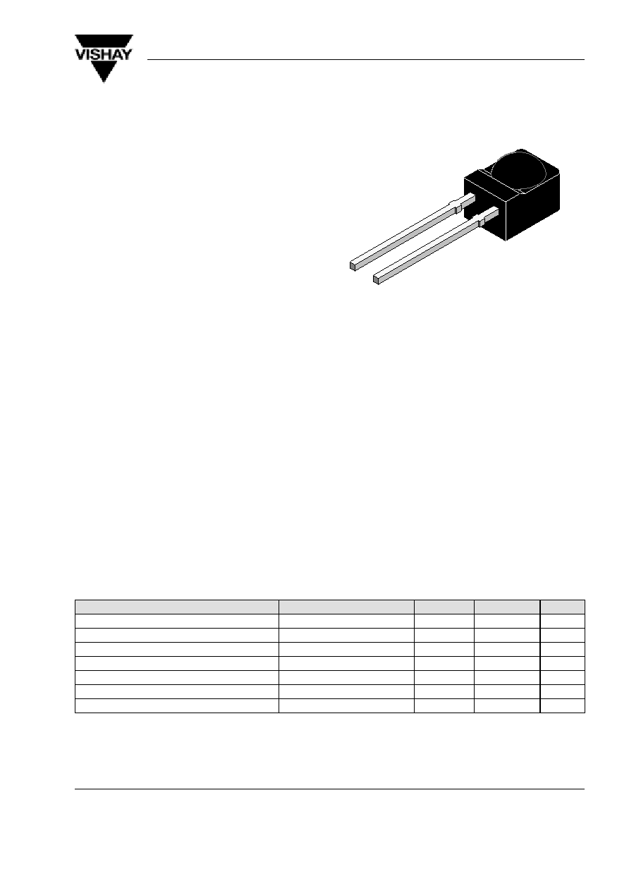
Silicon PIN Photodiode
Description
BPV22NF(L) is a high speed and high sensitive PIN
photodiode in a plastic package with a spherical side
view lens.
The epoxy package itself is an IR filter, spectrally
matched to GaAs on GaAs and GaAlAs on GaAlAs
IR emitters (
l
p
= 950 nm, s
rel
(
l
= 875 nm) > 90 %).
Lens radius and chip position are perfectly matched to
the chip size, giving high sensitivity without compro-
mising the viewing angle.
In comparison with flat packages the spherical
lens package achieves a sensitivity improvement
of 80%.
Features
D
Large radiant sensitive area (A=7.5 mm
2
)
D
Wide viewing angle
=
±
60
°
D
Improved sensitivity
D
Fast response times
D
Low junction capacitance
D
Plastic package with universal IR filter
D
Option "L": long lead package optional available
with suffix "L"; e.g.: BPV23FL
94 8633
Applications
Infrared remote control and free air transmission systems in combination with IR emitter diodes
(TSU., TSI., or TSH.Series). High sensitivity detector for high data rate transmission systems.
The IR filter matches perfectly to the high speed infrared emitters in the 830 nm to 880 nm wavelength range.
Absolute Maximum Ratings
T
amb
= 25
_
C
Parameter
Test Conditions
Symbol
Value
Unit
Reverse Voltage
V
R
60
V
Power Dissipation
T
amb
x
25
°
C
P
V
215
mW
Junction Temperature
T
j
100
°
C
Operating Temperature Range
T
amb
55...+100
°
C
Storage Temperature Range
T
stg
55...+100
°
C
Soldering Temperature
t
x
5 s
T
sd
260
°
C
Thermal Resistance Junction/Ambient
R
thJA
350
K/W

BPV22NF(L)
Vishay Telefunken
2 (6)
Rev. 3, 16-Nov-99
www.vishay.de
·
FaxBack +1-408-970-5600
Document Number 81509
Basic Characteristics
T
amb
= 25
_
C
Parameter
Test Conditions
Symbol
Min
Typ
Max
Unit
Forward Voltage
I
F
= 50 mA
V
F
1
1.3
V
Breakdown Voltage
I
R
= 100
m
A, E = 0
V
(BR)
60
V
Reverse Dark Current
V
R
= 10 V, E = 0
I
ro
2
30
nA
Diode Capacitance
V
R
= 0 V, f = 1 MHz, E = 0
C
D
70
pF
Serial Resistance
V
R
= 12 V, f = 1 MHz
R
S
400
W
Open Circuit Voltage
E
e
= 1 mW/cm
2
,
l
= 950 nm
V
o
370
mV
Temp. Coefficient of V
o
E
e
= 1 mW/cm
2
,
l
= 950 nm
TK
Vo
2.6
mV/K
Short Circuit Current
E
e
= 1 mW/cm
2
,
l
= 950 nm
I
k
80
m
A
Reverse Light Current
E
e
= 1 mW/cm
2
,
l
= 870 nm, V
R
= 5 V
I
ra
55
85
m
A
Temp. Coefficient of I
ra
E
e
= 1 mW/cm
2
,
l
= 950 nm, V
R
= 10 V
TK
Ira
0.1
%/K
Absolute Spectral Sensitivity
V
R
= 5 V,
l
= 870 nm
s(
l
)
0.57
A/W
y
V
R
= 5 V,
l
= 950 nm
s(
l
)
0.6
A/W
Angle of Half Sensitivity
±
60
deg
Wavelength of Peak Sensitivity
l
p
940
nm
Range of Spectral Bandwidth
l
0.5
790...1050
nm
Quantum Efficiency
l
= 950 nm
h
90
%
Noise Equivalent Power
V
R
= 10 V,
l
= 950 nm
NEP
4 x 10
14
W/
Hz
Detectivity
V
R
= 10 V,
l
= 950 nm
D
*
6x10
12
cm
Hz/
W
Rise Time
V
R
= 10 V, R
L
= 1k
W
,
l
= 820 nm
t
r
100
ns
Fall Time
V
R
= 10 V, R
L
= 1k
W
,
l
= 820 nm
t
f
100
ns
CutOff Frequency
V
R
= 12 V, R
L
= 1k
W
,
l
= 870 nm
f
c
4
MHz
V
R
= 12 V, R
L
= 1k
W
,
l
= 950 nm
f
c
1
MHz
BPV22NF(L)
Vishay Telefunken
3 (6)
Rev. 3, 16-Nov-99
www.vishay.de
·
FaxBack +1-408-970-5600
Document Number 81509
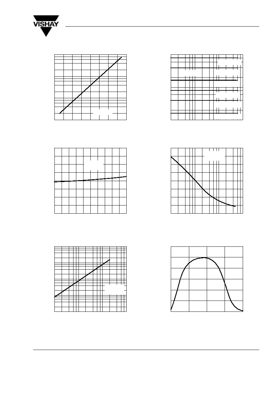
Typical Characteristics (T
amb
= 25
_
C unless otherwise specified)
20
40
60
80
1
10
100
1000
I Reverse Dark Current ( nA
)
ro
T
amb
Ambient Temperature (
°
C )
100
94 8403
V
R
=10V
Figure 1. Reverse Dark Current vs. Ambient Temperature
0
20
40
60
80
0.6
0.8
1.0
1.2
1.4
I Relative Reverse Light Current
ra rel
T
amb
Ambient Temperature (
°
C )
100
94 8409
V
R
=5V
l=950nm
Figure 2. Relative Reverse Light Current vs.
Ambient Temperature
0.01
0.1
1
0.1
1
10
100
1000
I Reverse Light Current (
A
)
ra
E
e
Irradiance ( mW / cm
2
)
10
94 8411
m
V
R
=5V
l=950nm
Figure 3. Reverse Light Current vs. Irradiance
0.1
1
10
1
10
100
V
R
Reverse Voltage ( V )
100
94 8412
I Reverse Light Current (
A
)
ra
m
0.5 mW/cm
2
0.05 mW/cm
2
0.2 mW/cm
2
0.02 mW/cm
2
0.1 mW/cm
2
1 mW/cm
2
l=950nm
Figure 4. Reverse Light Current vs. Reverse Voltage
0.1
1
10
0
20
40
60
80
C Diode Capacitance ( pF )
D
V
R
Reverse Voltage ( V )
100
94 8407
E=0
f=1MHz
Figure 5. Diode Capacitance vs. Reverse Voltage
750
850
950
1050
0
0.2
0.4
0.6
0.8
1.2
S ( ) Relative Spectral Sensitivity
rel
l Wavelength ( nm )
1150
94 8426
1.0
l
Figure 6. Relative Spectral Sensitivity vs. Wavelength
BPV22NF(L)
Vishay Telefunken
4 (6)
Rev. 3, 16-Nov-99
www.vishay.de
·
FaxBack +1-408-970-5600
Document Number 81509
0.4
0.2
0
0.2
0.4
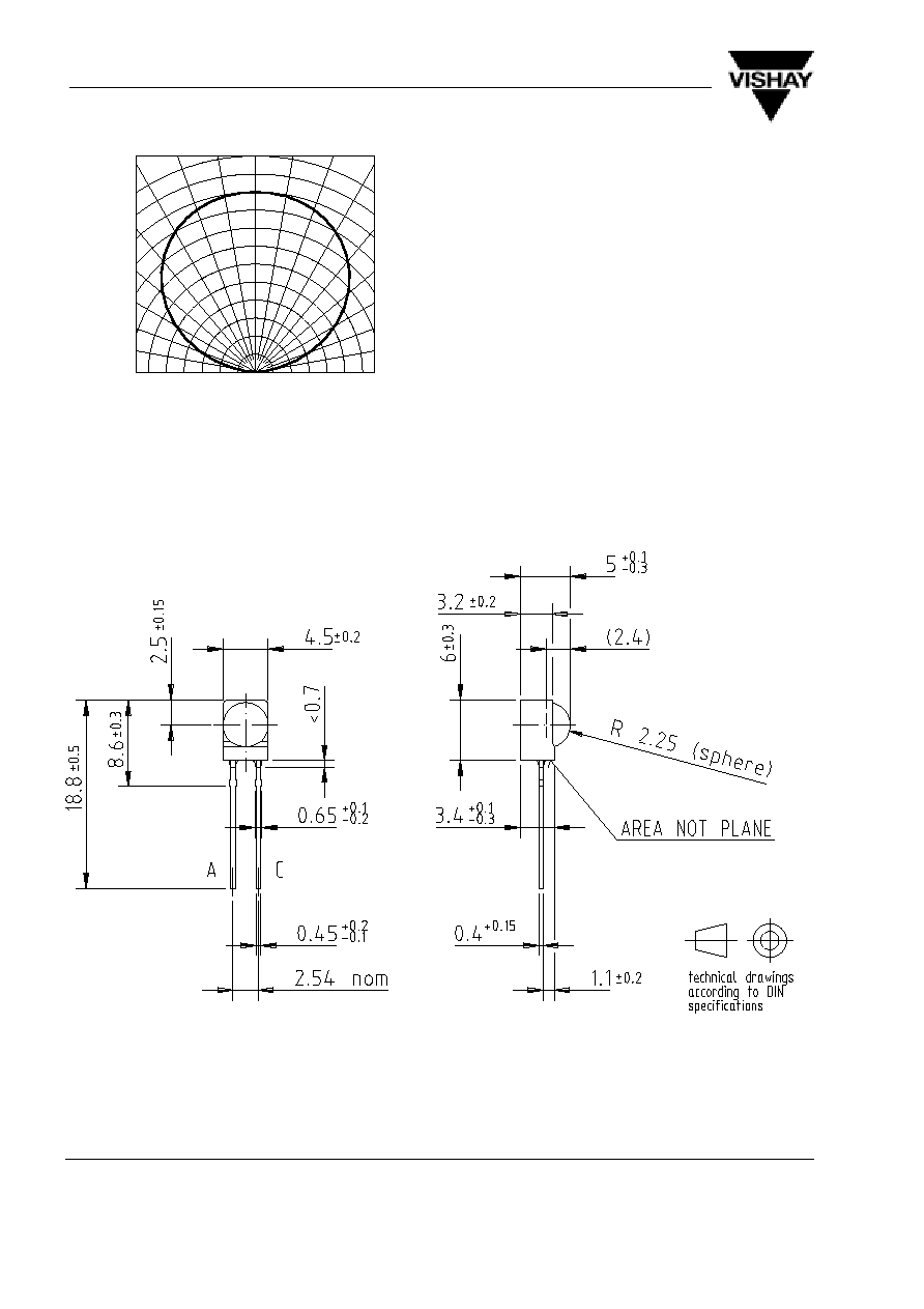
S Relative Sensitivity
rel
0.6
94 8413
0.6
0.9
0.8
0
°
30
°
10
°
20
°
40
°
50
°
60
°
70
°
80
°
0.7
1.0
Figure 7. Relative Radiant Sensitivity vs.
Angular Displacement
Dimensions BPV22NF in mm
95 11475
BPV22NF(L)
Vishay Telefunken
5 (6)
Rev. 3, 16-Nov-99
www.vishay.de
·
FaxBack +1-408-970-5600
Document Number 81509
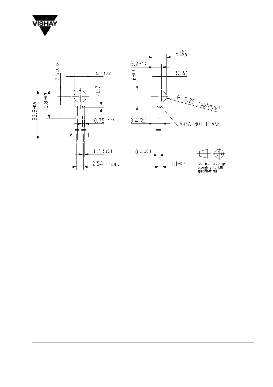
Dimensions BPV22NFL in mm
9612205