
www.vishay.com
For technical questions contact: aluminumcaps2@vishay.com
Document Number: 28345
106
Revision: 28-Oct-05
050/052 PED-PW
Vishay BCcomponents
Aluminum Capacitors
Power Eurodin Printed Wiring
FEATURES
À Polarized aluminum electrolytic capacitors,
non-solid electrolyte
À Large types, cylindrical aluminum case,
insulated with a blue sleeve
À Provided with keyed polarity
À 050 series also available in solder-lug (SL) versions
À Very long useful life:
15000 hours at 85 ░C
À Low ESR, high ripple current capability
À High resistance to shock and vibration.
APPLICATIONS
À Computer, telecommunication and industrial systems
À Smoothing and filtering
À Standard and switched mode power supplies
À Energy storage in pulse systems.
MARKING
The capacitors are marked (where possible)
with the following information:
À Rated capacitance (in ÁF).
À Tolerance on rated capacitance, code letter in accordance
with IEC 60062 (Q for
-10/+30%).
À Rated voltage (in V).
À Date code (YYMM).
À Name of manufacturer.
À Code for factory of origin.
À Polarity of the terminals and `-' sign to indicate the
negative terminal, visible from the top and/or side of the
capacitor.
À Code number.
À Climatic category in accordance with IEC 60068
.
QUICK REFERENCE DATA
DESCRIPTION
VALUE
050
052
Nominal case size
(
D Î L in mm)
25
Î 30
to 40
Î 100
Rated capacitance range
(E6 series), C
R
470
to 68000
ÁF
47
to 1000
ÁF
Tolerance on C
R
-10 to +30%
Rated voltage range, U
R
10 to 100 V
250 to 400 V
Category temperature range
-40 to +85 ░C
Endurance test at 85 ░C
5000 hours
Useful life at 85 ░C
15000 hours
Useful life at 40 ░C,
1.4
Î I
R
applied
250000 hours
Shelf life at 0 V, 85 ░C
500 hours
Based on sectional
specification
IEC 60384-4/EN130300
Climatic category IEC 60068
40/085/56
PW
PW
SL
Fig.1 Component outlines.
░
* Pb containing terminations are not RoHS compliant, exemptions may apply
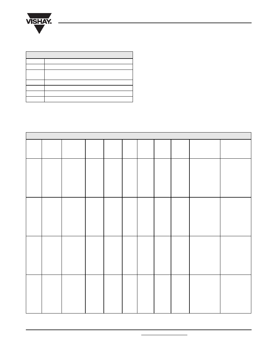
SELECTION CHART FOR C
R
, U
R
AND RELEVANT NOMINAL CASE SIZES FOR 050 SERIES (
D Î L in mm)
C
R
(
ÁF)
U
R
(V)
10
16
25
40
63
100
470
-
-
-
-
-
25
Î 30
680
-
-
-
-
25
Î 40
1000
-
-
-
-
25
Î 30
30
Î 40
1500
-
-
-
25
Î 30
25
Î 40
35
Î 40
2200
-
-
25
Î 30
25
Î 40
30
Î 40
35
Î 50
-
-
-
-
-
40
Î 40
3300
-
25
Î 30
25
Î 40
30
Î 40
35
Î 40
40
Î 50
4700
25
Î 30
25
Î 40
30
Î 40
35
Î 40
35
Î 50
40
Î 70
-
-
-
-
40
Î 40
-
6800
25
Î 40
30
Î 40
35
Î 40
35
Î 50
40
Î 50
40
Î 100
-
-
-
40
Î 40
-
-
10000
30
Î 40
35
Î 40
35
Î 50
40
Î 50
40
Î 70
-
-
-
40
Î 40
-
-
-
15000
35
Î 40
35
Î 50
40
Î 50
40
Î 70
40
Î 100
-
-
40
Î 40
-
-
-
-
22000
35
Î 50
40
Î 50
40
Î 70
40
Î 100
-
-
40
Î 40
-
-
-
-
-
33000
40
Î 50
40
Î 70
40
Î 100
-
-
-
47000
40
Î 70
40
Î 100
-
-
-
-
68000
40
Î 100
-
-
-
-
-
Available
Pb-free
RoHS*
COMPLIANT
Document Number: 28345
For technical questions contact: aluminumcaps2@vishay.com
www.vishay.com
Revision: 28-Oct-05
107
050/052 PED-PW
Aluminum Capacitors
Power Eurodin Printed Wiring
Vishay BCcomponents
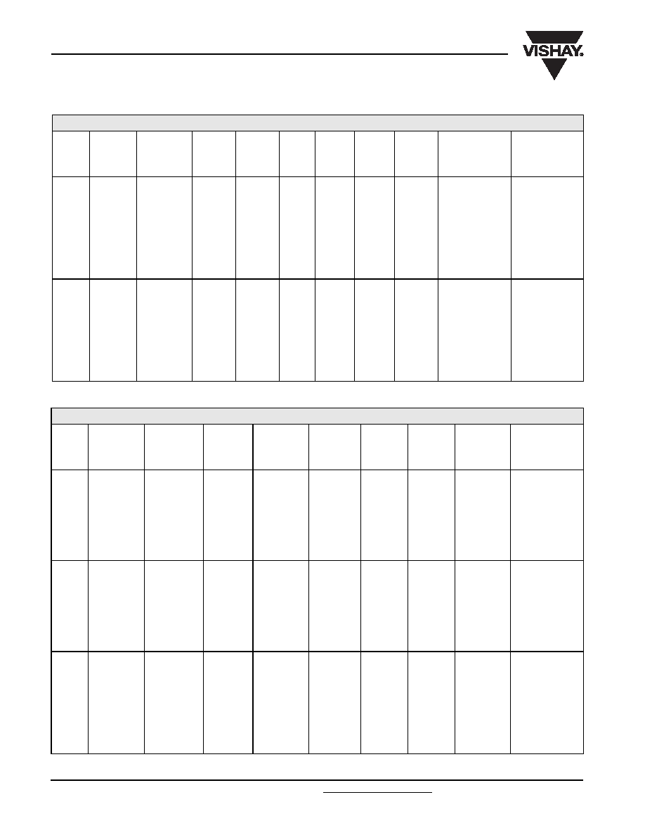
SELECTION CHART FOR C
R
, U
R
AND RELEVANT NOMINAL CASE SIZES FOR 052 SERIES (
D Î L in mm)
C
R
(
ÁF)
U
R
(V)
250
385
400
47
-
25
Î 30
25
Î 30
68
-
25
Î 40
25
Î 40
100
25
Î 30
30
Î 40
30
Î 40
150
25
Î 40
35
Î 40
35
Î 40
220
30
Î 40
35
Î 50
35
Î 50
-
40
Î 40
40
Î 40
330
35
Î 40
40
Î 50
40
Î 50
470
35
Î 50
40
Î 70
40
Î 70
40
Î 40
-
-
680
40
Î 50
-
40
Î 100
1000
40
Î 70
-
-
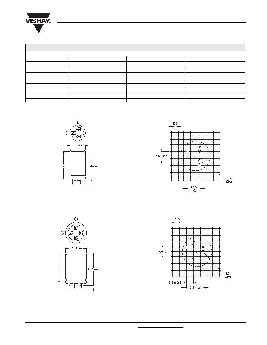
DIMENSIONS in millimeters AND AVAILABLE FORMS
Fig.2 Printed wiring pin version.
Case
D = 25 mm.
+
+
-
4.9 ▒ 0.2
-
Fig.3
Mounting hole diagram viewed from component side.
Case
D = 25 mm.
+
+
4.9 ▒ 0.2
-
3
Fig.4 Printed wiring pin version.
Case
D = 30 mm.
Fig.5
Mounting hole diagram viewed from component side.
-
Case
D = 30 mm.

www.vishay.com
For technical questions contact: aluminumcaps2@vishay.com
Document Number: 28345
108
Revision: 28-Oct-05
050/052 PED-PW
Vishay BCcomponents
Aluminum Capacitors
Power Eurodin Printed Wiring
Case
D = 35 mm.
D + 1 max.
CCA976-1
L
12
3
-
L
+ 5 max.
4.9 ▒ 0.2
Fig.6 Printed wiring pin version.
MGB267-1
15 0.1
1.3
(4x)
7.5 0.1
17.5 0.1
2.5
1
2
3
-
Fig.7 Mounting hole diagram viewed from component side.
Case
D = 35 mm.
20 0.1
1.3
(5x)
10 0.1
17.5 0.1
2.5
20 0.1
1
2
3
4
-
Case
D = 40 mm.
Fig.9 Mounting hole diagram viewed from
component side.
Fig.10 Solder-lug version (SL); only
available in 050 series.
▒
9 ▒ 1
MOUNTING
When a number of capacitors are connected in a bank, they must not be closer together than 15 mm, when no derating of ripple
current and/or temperature is applied.
Pin numbers 2, 3 and 4 (if present) must be free from the electrical circuit.
Table 1
Note
1. Not available in SL versions.
DIMENSIONS in millimeters, MASS AND PACKAGING QUANTITIES
NOMINAL
CASE SIZE
D Î L
D
max
L
max
SL VERSIONS
L
max
PW VERSIONS
MASS
(g)
PACKAGING QUANTITIES
(units per box)
CARDBOARD
BOX DIMENSIONS
L X W X H
25
Î 30
26
32
35
24
100
290
Î 280 Î 50
25
Î 40
26
42
45
28
100
290
Î 280 Î 60
30
Î 40
31
42
45
38
100
340
Î 330 Î 60
35
Î 40
36
42
45
51
50
390
Î 198 Î 60
35
Î 50
36
52
55
66
50
390
Î 198 Î 70
40
Î 40
1
41
-
45
78
50
440
Î 223 Î 60
40
Î 50
41
52
55
82
50
440
Î 223 Î 70
40
Î 70
41
72
75
110
25
230
Î 230 Î 90
40
Î 100
41
102
105
176
25
230
Î 230 Î 120
Document Number: 28345
For technical questions contact: aluminumcaps2@vishay.com
www.vishay.com
Revision: 28-Oct-05
109
050/052 PED-PW
Aluminum Capacitors
Power Eurodin Printed Wiring
Vishay BCcomponents
Note
1. Unless otherwise specified, all electrical values in
Tables 2 and 3 apply at T
amb
= 20 ░C, P = 86 to 106 kPa,
RH = 45 to 75%.
ORDERING EXAMPLE*
Electrolytic capacitor 050 series
10000 ÁF/25 V; - 10/+30%
Nominal case size:
35 Î 50 mm; PW version
Catalog number: 2222 050 56103.
* Note: To ensure delivery of lead (Pb)-free parts during the
transition period, please contact your Vishay sales agent.
ELECTRICAL DATA
SYMBOL
DESCRIPTION
C
R
rated capacitance at 100 Hz
I
R
rated RMS ripple current at 100 Hz,
85
░C or at 20kHz, 70 ░C
I
L1
max. leakage current after 1 minute at U
R
I
L5
max. leakage current after 5 minutes at U
R
ESR
max. equivalent series resistance at 100 Hz
Z
max. impedance at 10 kHz
Table 2
ELECTRICAL DATA AND ORDERING INFORMATION FOR 050 SERIES
U
R
(V)
C
R
100 Hz
(
F)
NOMINAL
CASE SIZE
D Î L
(mm)
I
R
100 Hz
85
░C
(A)
I
R
20 kHz
70
░C
(A)
I
L1
1 min
(mA)
I
L5
5 min
(mA)
ESR
100 Hz
(m
)
Z
10 kHz
(m
)
CATALOG
NUMBER SL
2222 050 .....
CATALOG
NUMBER PW
2222 050 .....
10
4700
25
Î 30
2.4
4.6
0.28
0.10
74
50
14472
54472
6800
25
Î 40
3.2
6.1
0.41
0.14
51
37
14682
54682
10000
30
Î 40
3.8
7.2
0.60
0.20
39
29
14103
54103
15000
35
Î 40
4.1
7.8
0.90
0.30
35
26
14153
54153
22000
35
Î 50
5.0
9.5
1.32
0.44
27
21
14223
54223
22000
40
Î 40
4.2
8.0
1.32
0.44
36
27
not available
44223
33000
40
Î 50
5.0
9.5
1.98
0.66
29
22
14333
54333
47000
40
Î 70
6.8
12.9
2.82
0.94
20
17
14473
54473
68000
40
Î 100
9.2
17.5
4.08
1.36
15
14
14683
54683
16
3300
25
Î 30
2.4
4.6
0.32
0.11
75
50
15332
55332
4700
25
Î 40
3.1
5.9
0.45
0.15
52
37
15472
55472
6800
30
Î 40
3.7
7.0
0.65
0.22
40
30
15682
55682
10000
35
Î 40
4.1
7.8
0.96
0.32
36
27
15103
55103
15000
35
Î 50
5.0
9.5
1.44
0.48
28
21
15153
55153
15000
40
Î 40
4.2
8.0
1.44
0.48
36
27
not available
45153
22000
40
Î 50
5.0
9.5
2.12
0.71
29
22
15223
55223
33000
40
Î 70
6.7
12.7
3.17
1.06
20
17
15333
55333
47000
40
Î 100
9.1
17.3
4.51
1.51
15
14
15473
55473
25
2200
25
Î 30
2.3
4.4
0.33
0.11
78
52
16222
56222
3300
25
Î 40
3.1
5.9
0.49
0.17
53
38
16332
56332
4700
30
Î 40
3.7
7.0
0.70
0.24
42
31
16472
56472
6800
35
Î 40
4.1
7.8
1.02
0.34
37
28
16682
56682
10000
35
Î 50
5.0
9.5
1.50
0.50
28
21
16103
56103
10000
40
Î 40
4.2
8.0
1.50
0.50
36
27
not available
46103
15000
40
Î 50
5.0
9.5
2.25
0.75
29
22
16153
56153
22000
40
Î 70
6.8
12.9
3.30
1.10
20
17
16223
56223
33000
40
Î 100
9.2
17.5
4.95
1.65
15
14
16333
56333
40
1500
25
Î 30
2.0
3.8
0.36
0.12
112
68
17152
57152
2200
25
Î 40
2.7
5.1
0.53
0.18
76
51
17222
57222
3300
30
Î 40
3.3
6.3
0.79
0.27
57
41
17332
57332
4700
35
Î 40
3.8
7.2
1.13
0.38
48
35
17472
57472
6800
35
Î 50
4.7
8.9
1.64
0.55
36
27
17682
57682
6800
40
Î 40
4.1
7.8
1.64
0.55
45
33
not available
47682
10000
40
Î 50
4.9
9.3
2.40
0.80
35
27
17103
57103
15000
40
Î 70
6.6
12.5
3.60
1.20
25
20
17153
57153
22000
40
Î 100
9.0
17.1
5.28
1.76
18
16
17223
57223
www.vishay.com
For technical questions contact: aluminumcaps2@vishay.com
Document Number: 28345
110
Revision: 28-Oct-05
050/052 PED-PW
Vishay BCcomponents
Aluminum Capacitors
Power Eurodin Printed Wiring
63
1000
25
Î 30
1.8
3.4
0.38
0.13
122
74
18102
58102
1500
25
Î 40
2.5
4.7
0.57
0.19
83
54
18152
58152
2200
30
Î 40
3.1
5.9
0.83
0.28
57
41
18222
58222
3300
35
Î 40
3.6
6.8
1.25
0.42
48
35
18332
58332
4700
35
Î 50
4.4
8.3
1.78
0.60
36
27
18472
58472
4700
40
Î 40
3.8
7.2
1.78
0.60
45
33
not available
48472
6800
40
Î 50
4.7
8.9
2.57
0.86
35
27
18682
58682
10000
40
Î 70
6.2
11.8
3.78
1.26
25
20
18103
58103
15000
40
Î 100
8.5
16.1
5.67
1.89
18
16
18153
58153
100
470
25
Î 30
1.4
2.7
0.28
0.10
247
172
19471
59471
680
25
Î 40
1.9
3.6
0.41
0.14
170
116
19681
59681
1000
30
Î 40
2.5
4.7
0.60
0.20
123
88
19102
59102
1500
35
Î 40
3.1
5.8
0.90
0.30
94
71
19152
59152
2200
35
Î 50
3.9
7.4
1.32
0.44
69
55
19222
59222
2200
40
Î 40
3.6
6.8
1.32
0.44
81
65
not available
49222
3300
40
Î 50
4.6
8.7
1.98
0.66
59
48
19332
59332
4700
40
Î 70
6.2
11.7
2.82
0.94
42
36
19472
59472
6800
40
Î 100
8.2
15.5
4.08
1.36
32
28
19682
59682
ELECTRICAL DATA AND ORDERING INFORMATION FOR 050 SERIES
U
R
(V)
C
R
100 Hz
(
F)
NOMINAL
CASE SIZE
D Î L
(mm)
I
R
100 Hz
85
░C
(A)
I
R
20 kHz
70
░C
(A)
I
L1
1 min
(mA)
I
L5
5 min
(mA)
ESR
100 Hz
(m
)
Z
10 kHz
(m
)
CATALOG
NUMBER SL
2222 050 .....
CATALOG
NUMBER PW
2222 050 .....
Table 3
ELECTRICAL DATA AND ORDERING INFORMATION FOR 052 SERIES
U
R
(V)
C
R
100 Hz
(
F)
NOMINAL
CASE SIZE
D Î L
(mm)
I
R
100 Hz
85
░C
(A)
I
R
20 kHz
70
░C
(A)
I
L1
1 min
(mA)
I
L5
5 min
(mA)
ESR
100 Hz
(m
)
Z
10 kHz
(m
)
CATALOG
NUMBER
2222 ... .....
250
100
25
Î 30
0.6
1.15
0.15
0.05
1800
1300
052 53101
150
25
Î 40
0.8
1.5
0.23
0.08
1100
850
052 53151
220
30
Î 40
1.0
1.9
0.33
0.11
750
550
052 53221
330
35
Î 40
1.4
2.65
0.49
0.17
500
400
052 53331
470
35
Î 50
1.8
3.4
0.70
0.24
360
290
052 53471
470
40
Î 40
1.8
3.4
0.70
0.24
420
350
052 43471
680
40
Î 50
2.3
4.4
1.02
0.34
250
190
052 53681
1000
40
Î 70
3.0
5.7
1.50
0.50
170
140
052 53102
385
47
25
Î 30
0.5
0.94
0.11
0.04
2370
1550
052 58479
68
25
Î 40
0.67
1.27
0.16
0.06
1640
1100
052 58689
100
30
Î 40
0.84
1.59
0.23
0.08
1275
950
052 58101
150
35
Î 40
1.13
2.14
0.34
0.11
850
635
052 58151
220
35
Î 50
1.48
2.8
0.50
0.17
580
430
052 58221
220
40
Î 40
1.48
2.8
0.50
0.17
580
430
052 48221
330
40
Î 50
1.97
3.73
0.75
0.25
385
300
052 58331
470
40
Î 70
2.7
5.11
1.06
0.36
270
215
052 58471
400
47
25
Î 30
0.47
0.89
0.11
0.04
2700
2125
052 56479
68
25
Î 40
0.63
1.29
0.16
0.06
1875
1470
052 56689
100
30
Î 40
0.84
1.59
0.24
0.08
1275
1000
052 56101
150
35
Î 40
1.13
2.14
0.36
0.12
850
665
052 56151
220
35
Î 50
1.41
2.67
0.52
0.17
650
450
052 56221
220
40
Î 40
1.41
2.67
0.52
0.17
650
450
052 46221
330
40
Î 50
1.86
3.52
0.79
0.26
435
315
052 56331
470
40
Î 70
2.54
4.81
1.12
0.37
305
225
052 56471
680
40
Î 100
3.56
6.75
1.63
0.54
210
155
052 56681