
UTC MPSA94
PNP EPITAXIAL SILICON TRANSISTOR
UTC
UNISONIC TECHNOLOGIES CO. LTD
1
QW-R201-021,A
HIGH VOLTAGE TRANSISTOR
FEATURES
*Collector-Emitter voltage:
V
CEO
=-400V
*Collector Dissipation:
Pc(max)=625mW
*Low collector-Emitter saturation voltage
APPLICATIONS
*Telephone switching
*High voltage switch
TO-92
1
1:EMITTER 2:BASE 3:COLLECTOR
ABSOLUTE MAXIMUM RATINGS
( Operating temperature range applies unless otherwise specified )
PARAMETER SYMBOL
RATING
UNIT
Collector-base voltage
V
CBO
-400 V
Collector-emitter voltage
V
CEO
-400 V
Emitter-base voltage
V
EBO
-6 V
Collector dissipation(Ta=25
�C
)
Pc 625
mW
Collector current
Ic
-300
mA
Junction Temperature
T
j
150
�C
Storage Temperature
T
STG
-55 ~ +150
�C
ELECTRICAL CHARACTERISTICS
(Tj=25
�C,unless otherwise specified)
PARAMETER
SYMBOL
TEST
CONDITIONS
MIN
TYP MAX UNIT
Collector-base breakdown voltage
BV
CBO
Ic=-100
�A,I
E
=0
-400
V
Collector-emitter breakdown voltage
BV
CEO
Ic=-1mA,I
B
=0 -400
V
Collector-emitter breakdown voltage
BV
CES
Ic=-100
�A,V
BE
=0
-400
V
Emitter-base breakdown voltage
BV
EBO
I
E
=-100
�A,Ic=0
-5 V
Collector cut-off current
I
CBO
V
CB
=-300V,I
E
=0
-100
nA
Collector cut-off current
I
CES
V
CB
=-400V,V
BE
=0
-1
�A
Emitter cut-off current
I
EBO
V
EB
=-4V,Ic=0
100
nA
DC current gain(note)
h
FE
V
CE
=-10V,Ic=-1mA
V
CE
=-10V,Ic=-10mA
V
CE
=-10V,Ic=-50mA
V
CE
=-10V,Ic=-100mA
60
70
70
40
300
Collector-emitter saturation voltage
V
CE
(sat)
Ic=-10mA,I
B
=-1mA
Ic=-50mA,I
B
=-5mA
-0.20
-0.5
V
Base-emitter saturation voltage
V
BE
(sat) Ic=-10mA,I
B
=-1mA
-0.75
V
Output capacitance
Cob
V
CB
=-20V,I
E
=0, f=1MHz
7
pF
Note:Pulse test:PW<300
�s,Duty Cycle<2%
UTC MPSA94
PNP EPITAXIAL SILICON TRANSISTOR
UTC
UNISONIC TECHNOLOGIES CO. LTD
2
QW-R201-021,A
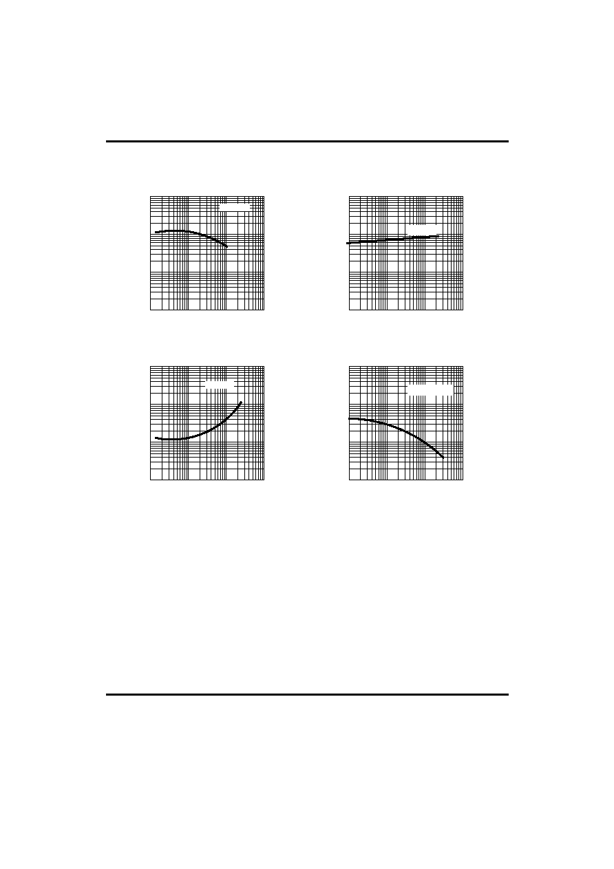
TYPICAL PARAMETERS PERFORMANCE
-1
-10
-100
-1000
1
10
100
1000
Ic,Collector current(mA)
H
FE
,
DC c
u
rre
n
t
Ga
i
n
Fig.1 Dc current gain
Ic,Collector current(mA)
-1
-10
-100
-1000
Ic,Collector current(mA)
-1
-10
-100
-0.01
-0.1
-1.0
-10
-0.01
-0.1
-1.0
-10
V
BE
(s
at) (V)
Fig.2 Base-emitter
saturation voltage
V
CE
(s
at) (V)
Fig.3 Collector-emitter
saturation voltage
Fig.4 Collector Output
capacitance
1
10
100
1000
-100
-10
-1
-0.1
Collector base voltage(V)
C
o
llector O
u
tput capacitance(pF)
V
CE
=-10V
Ic=10*I
B
Ic=10*I
B
I
E
=0,f=1MHz