GaAlAs HIGH POWER T-1 3/4 PACKAGE
INFRARED EMITTING DIODE
MIE-514H4
Description
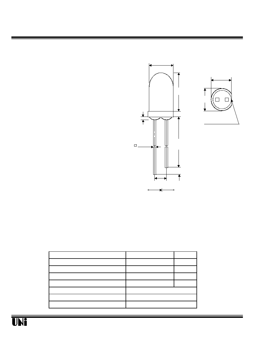
Package Dimensions
The MIE-514H4 is a GaAlAs infrared LED having
a peak wavelength at 850 nm . It feature ultra-high
power, high response speed and molded in water
clear plastic package, the MIE-514H4
have greatly
improved long-distance characteristics as well as
as significantly increased its range of applicability.
Features
l
Ultra-High radiant incidence
l
High response speed
l
High modulation bandwidth
l
Standard T-1 3/4 (
5mm ) package
l
Radiation angle : 15°
l
Peak wavelength
p
= 850 nm
Applications
l
Free air transmission systems with high -speed
response
l
SIR
Absolute Maximum Ratings
@ T
A
=25
o
C
Parameter
Maximum Rating
Unit
Power Dissipation
120
mW
Peak Forward Current(300pps,10
µ
s pulse)
1
A
Continuos Forward Current
100
mA
Reverse Voltage
5
V
Operating Temperature Range
-55
o
C to +100
o
C
Storage Temperature Range
-55
o
C to +100
o
C
Lead Soldering Temperature
260
o
C for 5 seconds
11/17/2000
Unity Opto Technology Co., Ltd.
C
5.05
(.200)
2.54NOM.
(.100)
SEE NOTE 2
7.62
(.300)
1.00
(.040)
0.50 TYP.
(.020)
23.40 MIN
(.920)
1.00MIN.
(.040)
A
FLAT DENOTES CATHODE
5.90
(.230)
5.47
(.215)
SEE NOTE 3
Unit: mm (inches)
NOTES :
1. Tolerance is ± 0.25 mm (.010") unless otherwise noted.
2. Protruded resin under flange is 1.5 mm (.059") max.
3. Lead spacing is measured where the leads emerge from the package.

MIE-514H4
Optical-Electrical Characteristics
@ T
A
=25
o
C
Parameter
Test Conditions
Symbol
Min.
Typ.
Max.
Unit
Radiant Intensity
I
F
=20mA
Ie
8
mW/sr
Forward Voltage
I
F
=50mA
V
F
1.5
1.8
V
Reverse Current
V
R
=5V
I
R
100
µ
A
Peak Wavelength
I
F
=20mA
p
850
nm
Spectral Bandwidth
I
F
=20mA
30
nm
Half View Angle
I
F
=20mA
2
1/2
15
deg .
Rise Time
I
F
=50mA
Tr
20
nsec
Fall Time
I
F
=50mA
Tf
30
nsec
Typical Optical-Electrical Characteristic Curves
11/17/2000
0
20
40
60
80
100
0.8
1.2
1.6
2.0
2.4
2.8
0
0.5
1
750
850
950
Wavelength (nm)
FIG.1 SPECTRAL DISTRIBUTION
Relative Radiant Intensity
Forward Voltage(V)
FIG.2 FORWARD CURRENT VS.
FORWARD VOLTAGE
Forward Current (mA)
0
0.5
1
1.5
2
2.5
3
-40
-20
0
20
40
60
Ambient Temperature T
A
(
o
C)
FIG.3 RELATIVE RADIANT INTENSITY
VS. AMBIENT TEMPERATURE
Output Power To Value
I
F
=20mA
0
1
2
3
4
5
0
20
40
60
80
100
Output Power Relative To
Value at I
F
=20mA
Forward Current (mA)
FIG.4 RELATIVE RADIANT INTENSITY
VS. FORWARD CURRENT
Relative Radiant Intensity
FIG.5 RADIATION DIAGRAM
0.5
0.3
0.1
0.2
0.4
0.6
30°
40°
90°
70°
60°
50°
80°
1.0
0.9
0.8
0° 10° 20°