TriQuint Semiconductor Texas : Phone (972)994 8465 Fax (972)994 8504 Web: www.triquint.com
Advance Product Information
January 18, 2005
1
Note: Devices designated as EPU are typically early in their characterization process prior to finalizing all electrical and process
specifications. Specifications are subject to change without notice
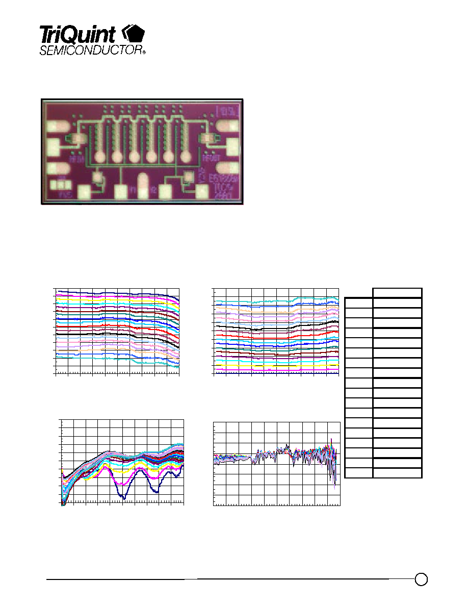
50 GHz Wideband Analog Attenuator TGL4203-EPU
Key Features and Performance
À
0.25um 3MI MMW pHEMT
À
Broadband Response DC to > 50 GHz
À
2dB typical Insertion Loss
À
17dB Variable Attenuation Range
À
15dB typical Return Loss
À
Bias: -1V to 0V
Primary Applications
À
Point to Point Radio
À
Fiber Optic
À
Wideband Military & Space
Chip Dimensions 1.7mm x 0.8 mm x 0.1mm
Typical Electrical Characteristics
-22
-20
-18
-16
-14
-12
-10
-8
-6
-4
-2
0
0
5 10 15 20 25 30 35 40 45 50
Frequency (GHz)
In
s
e
r
t
io
n
L
o
s
s
(
d
B
)
-30
-27
-24
-21
-18
-15
-12
-9
-6
-3
0
0
5 10 15 20 25 30 35 40 45 50
Frequency (GHz)
R
e
t
u
r
n
L
o
s
s
S
11
(
d
B
)
0
2
4
6
8
10
12
14
16
18
20
0
5 10 15 20 25 30 35 40 45 50
Frequency (GHz)
A
tte
n
u
a
t
i
o
n
(d
B
)
0
5
10
15
20
25
30
35
40
0
5 10 15 20 25 30 35 40 45 50
Frequency (GHz)
G
r
o
u
p
D
e
l
a
y (
p
sec)
V1 / V2
REF
0.000 / -1.000
1dB
-0.549 / -0.838
2dB
-0.606 / -0.752
3dB
-0.635 / -0.708
4dB
-0.659 / -0.680
5dB
-0.673 / -0.651
6dB
-0.679 / -0.626
7dB
-0.689 / -0.597
8dB
-0.705 / -0.578
9dB
-0.713 / -0.549
10dB
-0.719 / -0.518
11dB
-0.730 / -0.489
12dB
-0.744 / -0.461
13dB
-0.762 / -0.430
14dB
-0.794 / -0.392
15dB
-0.800 / -0.327
16dB
-0.851 / -0.267
17dB
-0.900 / -0.203
Bias Voltages Optimized
for Flatness of
Attenuation with respect
to Reference over
Frequency

TriQuint Semiconductor Texas : Phone (972)994 8465 Fax (972)994 8504 Web: www.triquint.com
Advance Product Information
January 18, 2005
2
Note: Devices designated as EPU are typically early in their characterization process prior to finalizing all electrical and process
specifications. Specifications are subject to change without notice
TABLE I
MAXIMUM RATINGS 1/
SYMBOL
PARAMETER
VALUE
NOTES
Attenuation Control Voltage Range
-5 to +1 V
| I
G1
|
Gate 1 Supply Current
2.2 mA
| I
G2
|
Gate 2 Supply Current
19.8 mA
P
IN
Input Continuous Wave Power
> 30dBm
P
D
Power Dissipation
TBD
T
CH
Operating Channel Temperature
150
0
C
2/ 3/
T
M
Mounting Temperature (30 Seconds)
320
0
C
T
STG
Storage Temperature
-65 to 150
0
C
1/
These ratings represent the maximum operable values for this device.
2/
Junction operating temperature will directly affect the device median time to failure (T
M
). For
maximum life, it is recommended that junction temperatures be maintained at the lowest possible
levels.
3/
These ratings apply to each individual FET.
TGL4203-EPU
TABLE II
ELECTRICAL CHARACTERISTICS
(Ta = 25
o
C Nominal)
PARAMETER
TEST CONDITIONS
TYP
UNIT
Attenuation Control Voltage
DC ~ 50 GHz
-1 to 0
V
IL
Insertion Loss
DC ~ 50 GHz
2
dB
Maximum Attenuation
DC ~ 50 GHz
17
dB
IRL
Input Return Loss
DC ~ 50 GHz
15
dB
ORL
Output Return Loss
DC ~ 50 GHz
15
dB
Pin1dB
Input Power @ 1dB Atten.
Change
5 to 25 GHz
*
dBm
Group Delay Variation
DC ~ 50 GHz
+/-5
psec
Max. Insertion Loss Ripple
(peak to peak)
DC ~ 50 GHz
0.5
dB
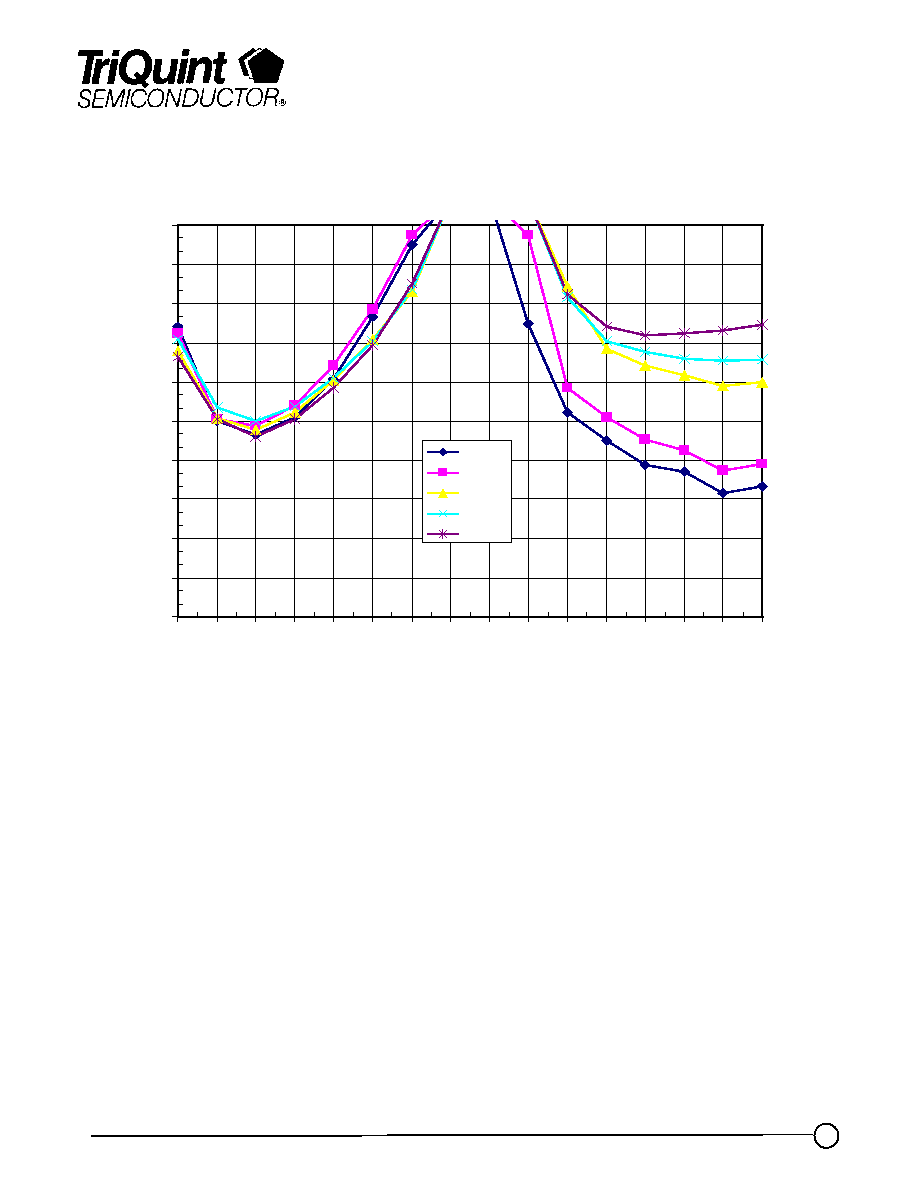
* Pin1dB varies depending on Attenuation State and frequency. See graphs on page 3 for details
TriQuint Semiconductor Texas : Phone (972)994 8465 Fax (972)994 8504 Web: www.triquint.com
Advance Product Information
January 18, 2005
3
Note: Devices designated as EPU are typically early in their characterization process prior to finalizing all electrical and process
specifications. Specifications are subject to change without notice
TGL4203-EPU
Typical Pin1dB vs Attenuation
Ta = 25
0
C Nominal
0
3
6
9
12
15
18
21
24
27
30
0
1
2
3
4
5
6
7
8
9
10
11
12
13
14
15
Attenuation (dB)
I
nput
P
o
w
e
r
@
1
d
B At
t
e
nuat
i
on
Change (
d
Bm
)
5 GHz
10 GHz
15 GHz
20 GHz
25 GHz
TriQuint Semiconductor Texas : Phone (972)994 8465 Fax (972)994 8504 Web: www.triquint.com
Advance Product Information
January 18, 2005
4
Note: Devices designated as EPU are typically early in their characterization process prior to finalizing all electrical and process
specifications. Specifications are subject to change without notice
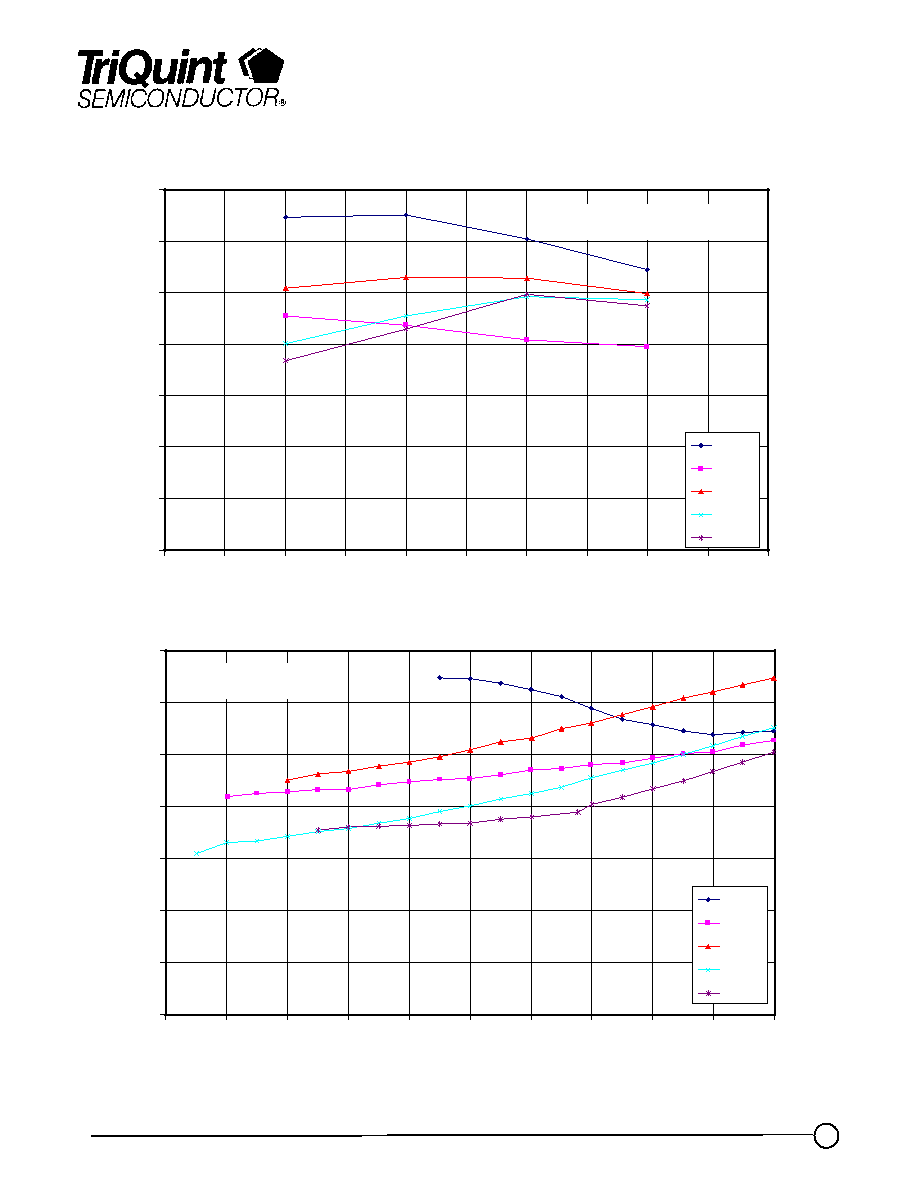
TGL4203-EPU
Typical Attenuator Input TOI vs. Attenuation
0
5
10
15
20
25
30
35
0
5
10
15
20
25
30
35
40
45
50
Frequency (GHz)
I
I
P3
(d
B
m
)
0dB
3dB
6dB
10dB
17dB
Pin = 0dBm
0
5
10
15
20
25
30
35
-10
-8
-6
-4
-2
0
2
4
6
8
10
Pin/tone (dBm)
IIP3
(
d
B
m
)
0dB
3dB
6dB
10dB
17dB
Freq = 10GHz

TriQuint Semiconductor Texas : Phone (972)994 8465 Fax (972)994 8504 Web: www.triquint.com
Advance Product Information
January 18, 2005
5
Note: Devices designated as EPU are typically early in their characterization process prior to finalizing all electrical and process
specifications. Specifications are subject to change without notice
TGL4203-EPU
Typical Attenuator Input TOI vs. Attenuation
0
5
10
15
20
25
30
35
-10
-8
-6
-4
-2
0
2
4
6
8
10
Pin/tone (dBm)
IIP
3 (
d
B
m
)
0dB
3dB
6dB
10dB
17dB
Freq = 20GHz
0
5
10
15
20
25
30
35
-10
-8
-6
-4
-2
0
2
4
6
8
10
Pin/tone (dBm)
IIP
3 (
d
B
m
)
0dB
3dB
6dB
10dB
17dB
Freq = 30GHz