
TriQuint Semiconductor Texas : Phone (972)994-8465 Fax (972)994 8504 Web: www.triquint.com
Advance Product Information
March 2, 2001
1
Single-Balanced Down Converter TGC1430E-EPU
Key Features and Performance
À
0.25um pHEMT Technology
À
20-40 GHz RF/LO Range
À
DC -1GHz IF
À
-8 dB conversion Gain at 500MHz IF
À
+15dBm LO drive
Note: Devices designated as EPU are typically early in their characterization process prior to finalizing all electrical and process
specifications. Specifications subject to change without notice
Primary Applications
À
Point-to-Point Radio
À
Point-to-Multipoint Communications
Chip Dimensions 1.26 mm x 1.19 mm
Conversion Gain vs IF Frequency
Conversion Gain vs LO Drive
0
5
10
15
20
25
30
35
40
45
50
2
6
10
14
18
22
26
30
34
38
42
46
50
Frequency (GHz)
Iso
l
a
t
i
o
n
(d
B
)
R2I
L2I
LO Drive Level = +15dBm
RF Drive Level = -15dBm
RF and LO to IF Isolation
-45
-40
-35
-30
-25
-20
-15
-10
-5
0
18
20
22
24
26
28
30
32
34
36
38
40
Frequency (GHz)
LO
R
e
t
u
r
n
Lo
s
s
(d
B)
12.5
15
17.5
Drive Level (dBm):
LO Return Loss
TriQuint Semiconductor Texas : Phone (972)994-8465 Fax (972)994 8504 Web: www.triquint.com
Advance Product Information
March 2, 2001
Note: Devices designated as EPU are typically early in their characterization process prior to finalizing all electrical and process
specifications. Specifications subject to change without notice
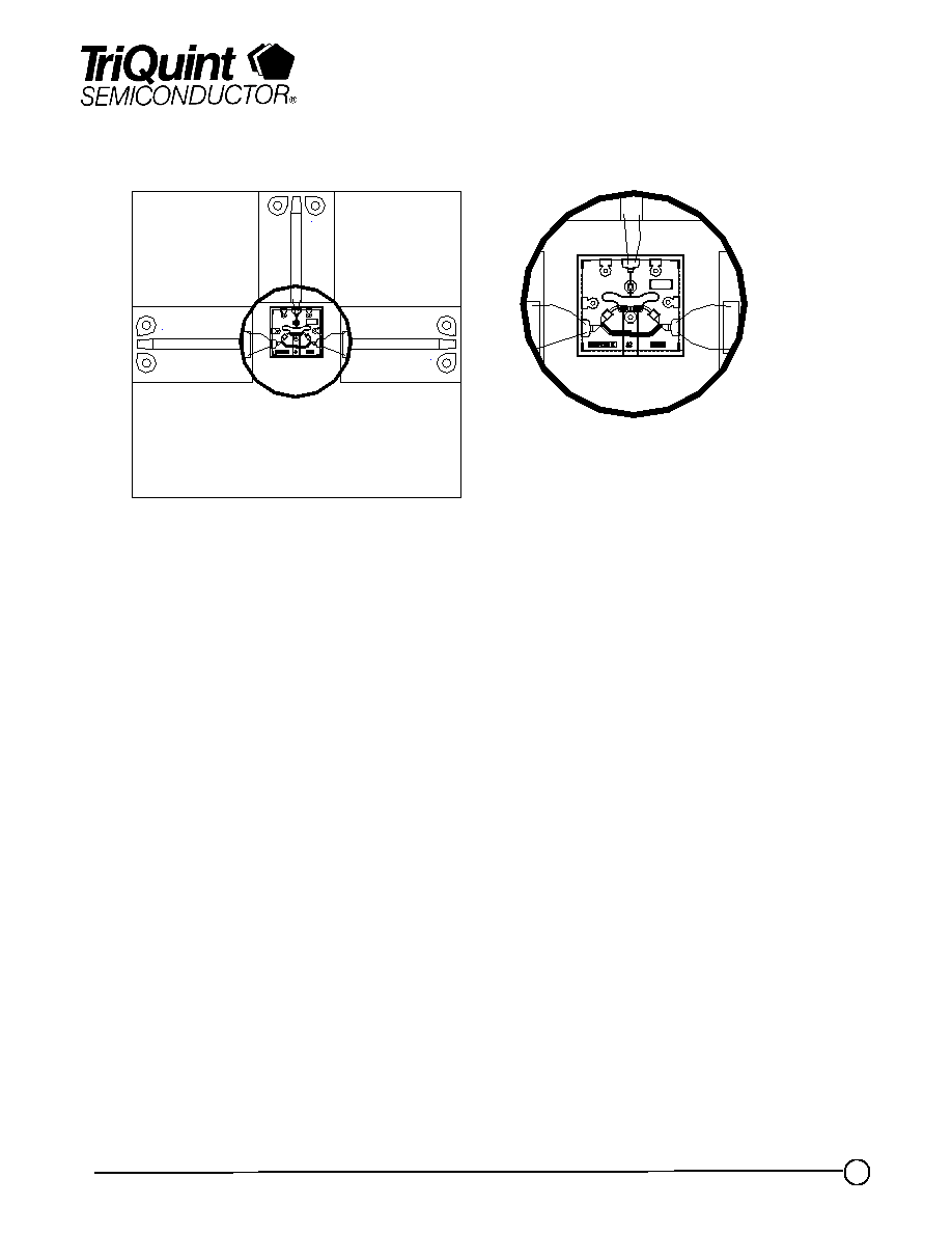
TGC1430E - Recommended Assembly Drawing
TGC1430E-EPU
RFout
RFin
LOin
TriQuint Semiconductor Texas : Phone (972)994-8465 Fax (972)994 8504 Web: www.triquint.com
Advance Product Information
March 2, 2001
Reflow process assembly notes:
À= AuSn (80/20) solder with limited exposure to temperatures at or above 300C
À= alloy station or conveyor furnace with reducing atmosphere
À= no fluxes should be utilized
À= coefficient of thermal expansion matching is critical for long-term reliability
À= storage in dry nitrogen atmosphere
Component placement and adhesive attachment assembly notes:
À= vacuum pencils and/or vacuum collets preferred method of pick up
À= avoidance of air bridges during placement
À= force impact critical during auto placement
À= organic attachment can be used in low-power applications
À= curing should be done in a convection oven; proper exhaust is a safety concern
À= microwave or radiant curing should not be used because of differential heating
À= coefficient of thermal expansion matching is critical
Interconnect process assembly notes:
À= thermosonic ball bonding is the preferred interconnect technique
À= force, time, and ultrasonics are critical parameters
À= aluminum wire should not be used
À= discrete FET devices with small pad sizes should be bonded with 0.0007-inch wire
À= maximum stage temperature: 200C
Assembly Process Notes
GaAs MMIC devices are susceptible to damage from Electrostatic Discharge. Proper precautions should
be observed during handling, assembly and test.
Note: Devices designated as EPU are typically early in their characterization process prior to finalizing all electrical and process
specifications. Specifications are subject to change without notice.
TGC1430E-EPU