
TriQuint Semiconductor Texas : Phone (972)994-8465 Fax (972)994 8504 Web: www.triquint.com
Advance Product Information
May 23, 2002
1
10 GB/s Differential Transimpedance Amplifier
TGA4805-EPU
Primary Applications
À
OC192/STM-64 Fiber-Optic Systems
Typical Measured Performance
Key Features
À
0.25 um pHEMT Technology
À
Frequency Range; 30 KHz to > 11GHz
À
1000
Differential Transimpedance
À
Average Input Eq. Noise: 9 pA /
Hz
À
Single Supply Operation
:
+5V @ 45 mA
À
Chip Size: 1.1 x 0.91 mm
Note: Devices designated as EPU are typically early in their characterization process prior to finalizing all electrical and process
specifications. Specifications are subject to change without notice.
Description
The TriQuint TGA4805-EPU is a
wideband transimpedance amplifier with
differential outputs that provides 500 Ohm
single-ended transimpedance into a
50 Ohm termination (1000 Ohm
differential into a 100 Ohm termination).
Typical output return loss is > 15 dB and
the average equivalent input noise current
is 9 pA/
Hz (1 GHz to 10 GHz). Typical
3dB BW is 30 KHz to 11GHz with 0.2 pF
of photodiode capacitance.
The TGA4805 operates from a single +5V
supply typically dissipating 225mW of DC
power. The device is backside grounded
with vias and requires no grounding bond
wires.
The TGA4805 requires off-chip decoupling
and the RF ports are DC coupled. Each
device is 100% RF tested on-wafer to
ensure performance compliance. The
device is available in die form.
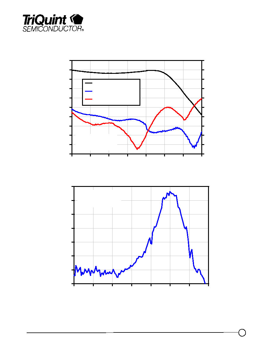
-10
0
10
20
30
40
50
60
1
3
5
7
9
11
13
15
Frequency (GHz)
G
r
oup D
e
l
a
y
R
i
ppl
e
(
p
s
)
CPD = 0.2 pF
RPD = 10 Ohm
33
36
39
42
45
48
51
54
57
60
63
1
3
5
7
9
11
13
15
Frequency (GHz)
T
r
an
sim
p
ed
an
ce (
d
B
-
Oh
m
)
-30
-27
-24
-21
-18
-15
-12
-9
-6
-3
0
Output Re
turn Los
s
(dB)
Differential TZ (dB-Ohm)
S22 Inverting Output
S22 Noninverting Output
CPD = 0.2 pF
RPD = 10 Ohm

TriQuint Semiconductor Texas : Phone (972)994-8465 Fax (972)994 8504 Web: www.triquint.com
Advance Product Information
May 23, 2002
2
TGA4805-EPU
TABLE I
MAXIMUM RATINGS
Symbol
Parameter 1/
Value
Notes
V
+
Positive Supply Voltage
+6.0V
I
+
Positive Supply Current
60 mA
2/
P
D
Power Dissipation
360 mW
P
IN
Input Continuous Wave Power
+15 dBm
T
CH
Operating Channel Temperature
150
░
C
3/, 4/
T
M
Mounting Temperature (30 seconds)
320
░
C
T
STG
Storage Temperature
-65
░
C to 150
░
C
1/
These values represent the maximum operable values of this device
2/
Total current for the entire MMIC
3/
These ratings apply to each individual FET
4/
Junction operating temperature will directly affect the device mean time to failure
(MTTF). For maximum life it is recommended that junction temperatures be
maintained at the lowest possible levels.
Note: Devices designated as EPU are typically early in their characterization process prior to finalizing all electrical and process
specifications. Specifications are subject to change without notice.
P a r a m e te r
U n its
C o n d itio n
T y p ic a l
T ra n s im p e d a n c e
d B
S in g le -e n d e d , R L = 5 0
5 4
T ra n s im p e d a n c e R ip p le
d B p p
1 G H z to 1 0 G H z
C P D = 0 .2 p F , R P D = 1 0
2
U p p e r 3 d B B a n d w id th
G H z
C P D = 0 .2 p F , R P D = 1 0
1 1
L o w e r 3 d B B a n d w id th *
k H z
C P D = 0 .2 p F , R P D = 1 0
3 0
G ro u p D e la y R ip p le
p s
1 G H z to 8 G H z
C P D = 0 .2 p F , R P D = 1 0
+ 1 0
E q . In p u t N o is e C u r re n t
p A /
H z
A v e : 1 G H z to 1 0 G H z
C P D = 0 .2 p F
9
O u tp u t R e tu rn L o s s
d B
3 0 K H z to 1 2 G H z
1 5
S u p p ly V o lta g e
V
5 .0
S u p p ly C u rre n t
m A
4 5
TABLE II
ELECTRICAL CHARACTERISTICS
(Ta = 25
o
C ▒ 5
o
C)
Vd = 5V
* Set by off-chip capacitance
Note: Electrical parameters are calculated for a photodiode equivalent circuit of 0.2pF and 10
TriQuint Semiconductor Texas : Phone (972)994-8465 Fax (972)994 8504 Web: www.triquint.com
Advance Product Information
May 23, 2002
3
TGA4805-EPU
33
36
39
42
45
48
51
54
57
60
63
1
3
5
7
9
11
13
15
Frequency (GHz)
Transimpedance (dB-Ohm)
-30
-27
-24
-21
-18
-15
-12
-9
-6
-3
0
Output Return Loss (dB)
Differential TZ (dB-Ohm)
S22 Inverting Output
S22 Noninverting Output
CPD = 0.2 pF
RPD = 10 Ohm
-10
0
10
20
30
40
50
60
1
3
5
7
9
11
13
15
Frequency (GHz)
Gr
oup Delay Ripple (ps)
CPD = 0.2 pF
RPD = 10 Ohm
Measured Fixtured Data
Note: Devices designated as EPU are typically early in their characterization process prior to finalizing all electrical and process
specifications. Specifications are subject to change without notice.
TriQuint Semiconductor Texas : Phone (972)994-8465 Fax (972)994 8504 Web: www.triquint.com
Advance Product Information
May 23, 2002
4
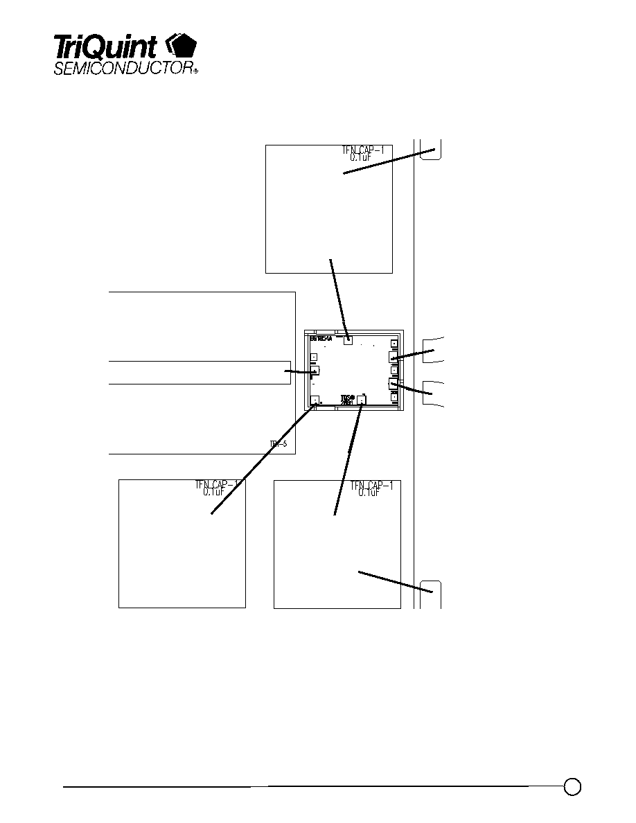
Chip Assembly and Bonding Diagram
GaAs MMIC devices are susceptible to damage from Electrostatic Discharge. Proper precautions should
be observed during handling, assembly and test.
Note: Devices designated as EPU are typically early in their characterization process prior to finalizing all electrical and process
specifications. Specifications are subject to change without notice.
TGA4805-EPU
RF IN
+ 5V
Voffset
Adjust
0.1
Á
F
- RF OUT
+ RF OUT
0.1
Á
F
0.1
Á
F

TriQuint Semiconductor Texas : Phone (972)994-8465 Fax (972)994 8504 Web: www.triquint.com
Advance Product Information
May 23, 2002
5
Mechanical Drawing
Note: Devices designated as EPU are typically early in their characterization process prior to finalizing all electrical and process
specifications. Specifications are subject to change without notice.
TGA4805-EPU
Note: Devices designated as EPU are typically early in their characterization process prior to finalizing all electrical and process
specifications. Specifications are subject to change without notice.
GaAs MMIC devices are susceptible to damage from Electrostatic Discharge. Proper precautions should
be observed during handling, assembly and test.