Advance Product Information
October 13, 2003
1
Note: Devices designated as EPU are typically early in their characterization process prior to finalizing all electrical and process
specifications. Specifications are subject to change without notice.
TriQuint Semiconductor Texas Phone: (972)994-8465 Fax: (972)994-8504 Email: info-mmw@tqs.com Web: www.triquint.com
10 Gb/s Single Ended to Differential Amplifier TGA2951-EPU
Key Features and Performance
À
3dB Bandwidth: 9.5 GHz
À
21 dB Differential Gain
À
Single Ended In, Differential Out
À
Crossing Adjustment (XOVR)
À
Output Level Adjust (OUTLVL)
À
Up to 1.5 Vpp Differential Out
À
Output Power Detector
À
0.25Ám 3MI pHEMT Technology
À
Self Bias: V
D
= 5V, I
D
= 72 mA
À
Chip dimensions: 1.00 x 1.10 x 0.1 mm
(0.039 x 0.043 x 0.004 inches)
Preliminary Measured Performance
Bias Conditions: V
D
= 5V, I
D
= 72 mA
Primary Applications
À
OC-192/STM-64 Fiber Optic
Systems
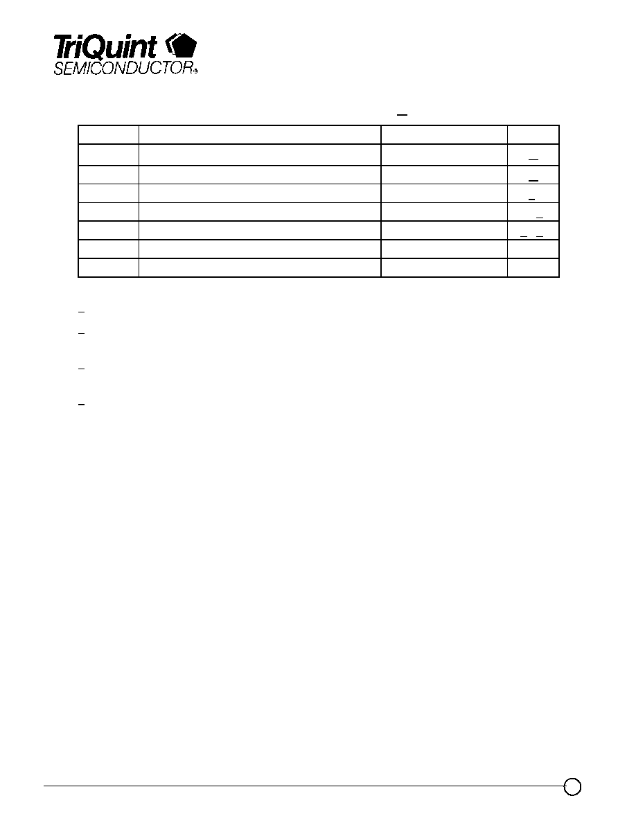
10.7 Gb/s 70mVpp Input (N/C) Vadj
0
3
6
9
12
15
18
21
0
2
4
6
8
10
12
14
16
18
20
Frequency (GHz)
Single
Ende
d Ga
in (dB)
RF Out (+) S21
RF Out (-) S31
Product Description
The TriQuint TGA2951-EPU is a
Single Ended to
Differential Amplifier
for OC-192/STM-64 Fiber Optic
System receive chains. The TGA2951-EPU
provides a Single ended to differential Conversion
with gain.
The part is designed using TriQuint's proven
standard 0.25 um gate Power pHEMT production
process.
The TGA2951-EPU is 100% DC and RF tested
on-wafer to ensure performance compliance.
Advance Product Information
October 13, 2003
2
Note: Devices designated as EPU are typically early in their characterization process prior to finalizing all electrical and process
specifications. Specifications are subject to change without notice.
TriQuint Semiconductor Texas Phone: (972)994-8465 Fax: (972)994-8504 Email: info-mmw@tqs.com Web: www.triquint.com
TGA2951-EPU
TABLE I
MAXIMUM RATINGS 1/
SYMBOL
PARAMETER
VALUE
NOTES
V
+
Positive Supply Voltage
5.5 V
2/
I
+
Positive Supply Current
84 mA
2/
P
IN
Input Continuous Wave Power
15 dBm
2/
P
D
Power Dissipation
462 mW
2/, 3/
T
CH
Operating Channel Temperature
150
░
C
4/, 5/
T
M
Mounting Temperature (30 Seconds)
320
░
C
T
STG
Storage Temperature
-65 to 150
░
C
1/
These ratings represent the maximum operable values for this device.
2/
Combinations of supply voltage, supply current, input power, and output power shall not
exceed P
D
.
3/
When operated at this power dissipation with a base plate temperature of 70
░
C, the median
life is 1 E+6 hours.
4/
Junction operating temperature will directly affect the device median time to failure (T
M
). For
maximum life, it is recommended that junction temperatures be maintained at the lowest
possible levels.
5/
These ratings apply to each individual FET.

Advance Product Information
October 13, 2003
3
Note: Devices designated as EPU are typically early in their characterization process prior to finalizing all electrical and process
specifications. Specifications are subject to change without notice.
TriQuint Semiconductor Texas Phone: (972)994-8465 Fax: (972)994-8504 Email: info-mmw@tqs.com Web: www.triquint.com
TABLE II
RF CHARACTERIZATION TABLE
(T
A
= 25
░
C, Nominal)
Bias Conditions: V
D
= 5V, I
D
= 72 mA
Parameter
Conditions
Typical
Units
Differential Gain
1 GHz
21
dB
3dB Bandwidth
9.5
GHz
Small Signal Gain Delta
1 ¡ 9 GHz
▒
0.25
dB
Input Return Loss
1 ¡ 9 GHz
15
dB
Output Return Loss (S22, S33)
1 ¡ 9 GHz
15
dB
Insertion Phase Delta
1 ¡ 9 GHz
180
▒
2
deg
Group Delay Ripple
Reference to 1 GHz
▒
4
ps
Nominal Crossing Level
Over Output
Operating Range
50
%
Crossing Level Adjustment
▒
10
%
Output Adjustment
15
dB
Detector Output
Output levels
0 ¡ 650 Vpp S/E
0 ¡ 150
mV
Note: Table II lists the RF Characteristics of typical devices as determined by fixtured
measurements.
TGA2951-EPU
Advance Product Information
October 13, 2003
4
Note: Devices designated as EPU are typically early in their characterization process prior to finalizing all electrical and process
specifications. Specifications are subject to change without notice.
TriQuint Semiconductor Texas Phone: (972)994-8465 Fax: (972)994-8504 Email: info-mmw@tqs.com Web: www.triquint.com
Preliminary Measured Performance
Bias Conditions: V
D
= 5V, I
D
= 72 mA
-30
-25
-20
-15
-10
-5
0
0
2
4
6
8
10
12
14
16
18
20
Frequency (GHz)
R
e
turn Loss (dB
)
RF Out (+) S22
RF Out (-) S33
RF In
0
3
6
9
12
15
18
21
0
2
4
6
8
10
12
14
16
18
20
Frequency (GHz)
Single Ended Gain (dB
)
RF Out (+) S21
RF Out (-) S31
TGA2951-EPU
0
2
4
6
8
10
12
14
16
18
20
Frequency (GHz)
0
20
40
60
80
100
120
140
160
180
200
G
r
ou
p D
e
l
a
y
(
p
s
)

Advance Product Information
October 13, 2003
5
Note: Devices designated as EPU are typically early in their characterization process prior to finalizing all electrical and process
specifications. Specifications are subject to change without notice.
TriQuint Semiconductor Texas Phone: (972)994-8465 Fax: (972)994-8504 Email: info-mmw@tqs.com Web: www.triquint.com
-30
-25
-20
-15
-10
-5
0
0
2
4
6
8
10
12
14
16
18
20
Frequency (GHz)
Input R
e
tun Loss (dB
)
-50 deg C
-25 deg C
0 deg C
25 deg C
75 deg C
-30
-25
-20
-15
-10
-5
0
0
2
4
6
8
10
12
14
16
18
20
Frequency (GHz)
P
o
sitive Output Retur
n
Loss (dB)
-50 deg C
-25 deg C
0 deg C
25 deg C
75 deg C
-5
0
5
10
15
20
0
2
4
6
8
10
12
14
16
18
20
Frequency (GHz)
S
i
ngl
e E
nded G
a
i
n
(
d
B
)
-50 deg C
-25 deg C
0 deg C
25 deg C
75 deg C
Preliminary Measured Performance
Bias Conditions: V
D
= 5V, I
D
= 72 mA
TGA2951-EPU