Advance Product Information
November 12, 2004
1
TriQuint Semiconductor Texas Phone: (972)994-8465 Fax: (972)994-8504 Email: info-mmw@tqs.com Web: www.triquint.com
X-Band Driver Amplifier
TGA2700
Key Features
À
Frequency Range: 7-13 GHz
À
25 dB Nominal Gain
À
30dBm Output Power @ Pin=10dBm, Midband
À
12 dB Input Return Loss
À
10 dB Output Return Loss
À
0.25 um 3MI pHEMT Technology
À
Nominal Bias 9V @ 300 mA/225 mA
À
Chip Dimensions: 1.57 x 1.33 x 0.10 mm
(0.062 x 0.052 x 0.004 in)
Product Description
The TriQuint TGA2700-EPU is an X-band Driver
Amplifier that operates between 7-13 GHz, The
Driver Amplifer is designed using TriQuint's
proven standard 0.25 um gate pHEMT production
process.
The TGA2700-EPU provides typical 30dBm
output power at +10 dBm input power @ 300mA
and has a small signal gain of 25 dB.
The TGA2700-EPU is 100% DC and RF tested
on-wafer to ensure performance compliance.
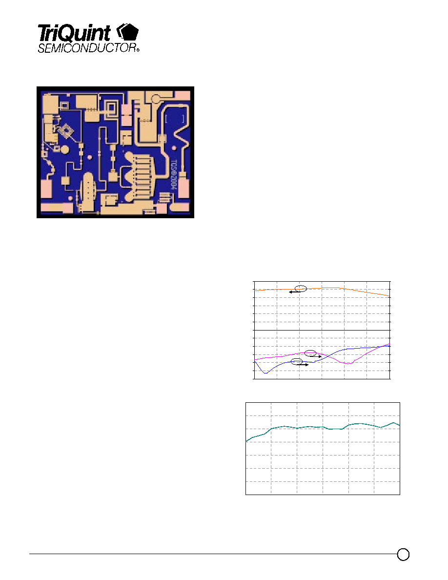
Measured Fixtured Data
Bias Conditions: Vd = 9V, Idq= 300mA
Primary Applications
À
X-band Driver
À
Point-to-Point Radio
-30
-25
-20
-15
-10
-5
0
5
10
15
20
25
30
7
8
9
10
11
12
13
Frequency (GHz)
G
a
in (dB)
-30
-25
-20
-15
-10
-5
0
5
10
15
20
25
30
Re
turn Los
s
(dB)
Input
Output
Gain
Note: This Device is early in the characterization process prior to finalizing all electrical specifications. Specifications are subject to
change without notice.
20
22
24
26
28
30
32
34
7
8
9
10
11
12
13
Frequency (GHz)
Ou
t
p
u
t
Po
we
r
a
t
Pin
= 1
0
d
Bm (
d
Bm)

Advance Product Information
November 12, 2004
2
TriQuint Semiconductor Texas Phone: (972)994-8465 Fax: (972)994-8504 Email: info-mmw@tqs.com Web: www.triquint.com
TABLE I
MAXIMUM RATINGS
Symbol
Parameter 1/
Value
Notes
V
+
Positive Supply Voltage
10 V
2/
V
-
Negative Supply Voltage Range
-5V TO 0V
I
+
Positive Supply Current
536 mA
2/
| I
G
|
Gate Supply Current
14 mA
P
IN
Input Continuous Wave Power
20 dBm
2/
P
D
Power Dissipation
2.7 W
2/, 3/
T
CH
Operating Channel Temperature
150
0
C
4/, 5/
T
M
Mounting Temperature (30 Seconds)
320
0
C
T
STG
Storage Temperature
-65 to 150
0
C
1/
These ratings represent the maximum operable values for this device.
2/
Combinations of supply voltage, supply current, input power, and output power shall not
exceed P
D
.
3/
When operated at this bias condition with a base plate temperature of 55
0
C,
the median life is 1E+6 hours.
4/ Junction operating temperature will directly affect the device median time to failure (T
M
).
For maximum life, it is recommended that junction temperatures be maintained at the lowest
possible levels.
5/
These ratings apply to each individual FET.
TGA2700-EPU
TABLE II
DC PRO BE TESTS
(T
A
= 25
░
C, Nominal)
Symbol
Param eter
Minim um
M aximum
Value
Idss
Saturated Drain Current
75
353
mA
Gm
Transconductance
165
398
mS
V
P
Pinch-off Voltage
-1.5
-0.5
V
B
VGS
Breakdown Voltage gate-source
-30
-8
V
B
VGD
Breakdown Voltage gate-drain
-30
-12
V

Advance Product Information
November 12, 2004
3
TriQuint Semiconductor Texas Phone: (972)994-8465 Fax: (972)994-8504 Email: info-mmw@tqs.com Web: www.triquint.com
TABLE III
RF CHARACTERIZATION TABLE
(T
A
= 25
░
C, Nominal)
Vd = 9 V, Id = 300 mA
SYMBOL
PARAMETER
TEST
CONDITION
NOMINAL
UNITS
Gain
Small Signal Gain
f = 7-13 GHz
25
dB
IRL
Input Return Loss
f = 7-13 GHz
12
dB
ORL
Output Return Loss
f = 7-13 GHz
10
dB
P
sat
Saturated Output Power
f = 8-13 GHz
30
dBm
TOI
Output TOI @ Pin = -5dBm
f = 8-12 GHz
> 36
dBm
PAE
Power Added Efficiency
f = 12 GHz
27
%
TABLE IV
THERMAL INFORMATION
Parameter
Test Conditions
T
baseplate
(
o
C)
T
CH
(
o
C)
R
T
JC
(
q
C/W)
T
M
(HRS)
Vd = 9 V
I
D
= 225 mA
Pdiss = 2.0 W
70
140
2.4 E+6
R
JC
Thermal
Resistance
(channel to backside
of package)
Vd = 9 V
I
D
= 300 mA
Pdiss = 2.7 W
55
150
34.7
1 E+6
Note: Assumes eutectic attach using 1.5 mil 80/20 AuSn mounted to a 20 mil
CuMo Carrier. Worst case condition with no RF applied, 100% of DC power is dissipated.
TGA2700-EPU

Advance Product Information
November 12, 2004
4
TriQuint Semiconductor Texas Phone: (972)994-8465 Fax: (972)994-8504 Email: info-mmw@tqs.com Web: www.triquint.com
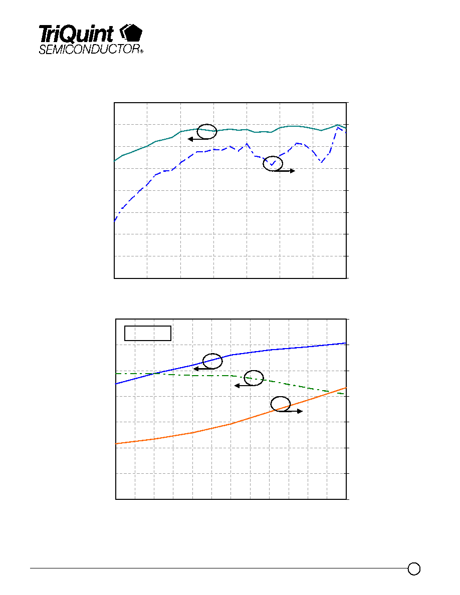
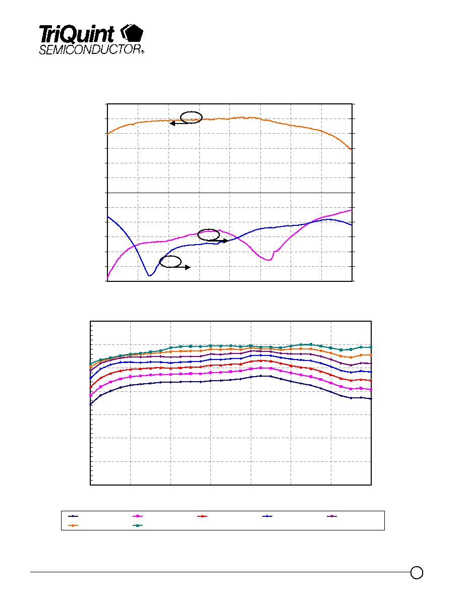
TGA2700-EPU
Typical Fixtured Performance
Bias Conditions: Vd = 9V, Idq = 300mA
-30
-25
-20
-15
-10
-5
0
5
10
15
20
25
30
6
7
8
9
10
11
12
13
14
Frequency (GHz)
Gain (dB)
-30
-25
-20
-15
-10
-5
0
5
10
15
20
25
30
Return Loss (dB)
Input
Output
Gain
0
5
10
15
20
25
30
35
6
7
8
9
10
11
12
13
Frequency (GHz)
Pout (dB
m
)
Pin = -2 dBm
Pin = 0 dBm
Pin = 2 dBm
Pin = 4 dBm
Pin = 6 dBm
Pin = 8 dBm
Pin = 10 dBm
Advance Product Information
November 12, 2004
5
TriQuint Semiconductor Texas Phone: (972)994-8465 Fax: (972)994-8504 Email: info-mmw@tqs.com Web: www.triquint.com
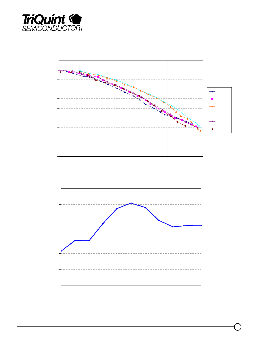
Typical Fixtured Performance
Bias Conditions: Vd = 9V, Idq = 300mA
10
13
16
19
22
25
28
31
34
6
7
8
9
10
11
12
13
Frequency (GHz)
Pout @ Pin = +10dBm (dBm)
0
5
10
15
20
25
30
35
40
PAE (
%
)
Output Power
PAE
TGA2700-EPU
0
5
10
15
20
25
30
35
-2
-1
0
1
2
3
4
5
6
7
8
9
10
Input Power (dBm)
Pout (dBm) & Gai
n
(dB)
0.2
0.25
0.3
0.35
0.4
0.45
0.5
0.55
Id (
A
)
Output Power
Id
Gain
@ 10 GHz

Advance Product Information
November 12, 2004
6
TriQuint Semiconductor Texas Phone: (972)994-8465 Fax: (972)994-8504 Email: info-mmw@tqs.com Web: www.triquint.com
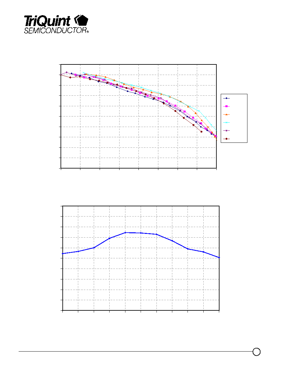
Typical Fixtured Performance
Bias Conditions: Vd = 9V, Idq = 300mA
TGA2700-EPU
-80
-70
-60
-50
-40
-30
-20
-10
0
6
7
8
9
10
11
12
13
14
Frequency (GHz)
Input Return Loss (dB)
-40
-30
-20
-10
0
10
20
30
40
Output Return Loss (dB)
-40 Deg C - S11
Room Temp. - S11
+75 deg. C - S11
-40 Deg C - S22
Room Temp. - S22
+75 deg. C - S22
10
12
14
16
18
20
22
24
26
28
30
6
7
8
9
10
11
12
13
14
Frequency (GHz)
Gain (
d
B)
-40 deg C
Room
Temp.
+75 deg C
Advance Product Information
November 12, 2004
7
TriQuint Semiconductor Texas Phone: (972)994-8465 Fax: (972)994-8504 Email: info-mmw@tqs.com Web: www.triquint.com
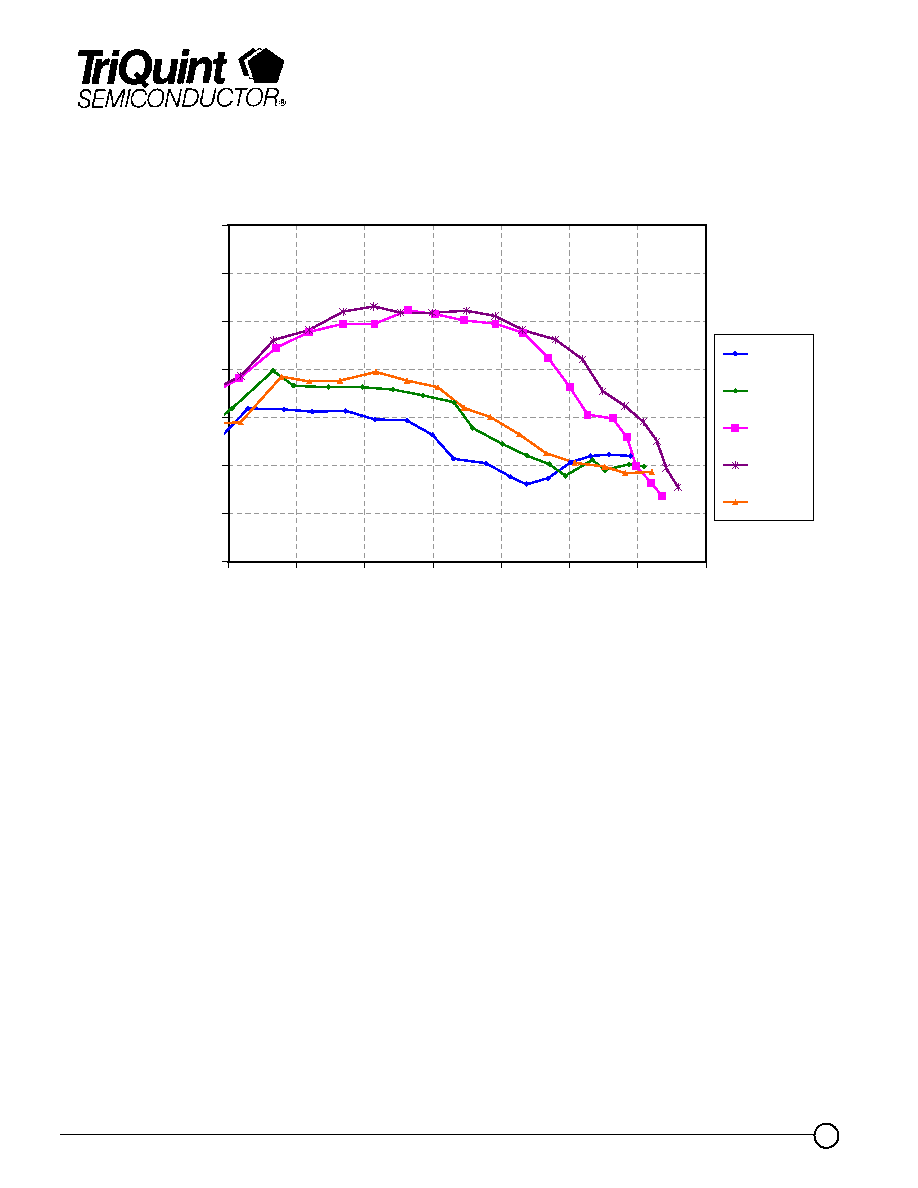
TGA2700-EPU
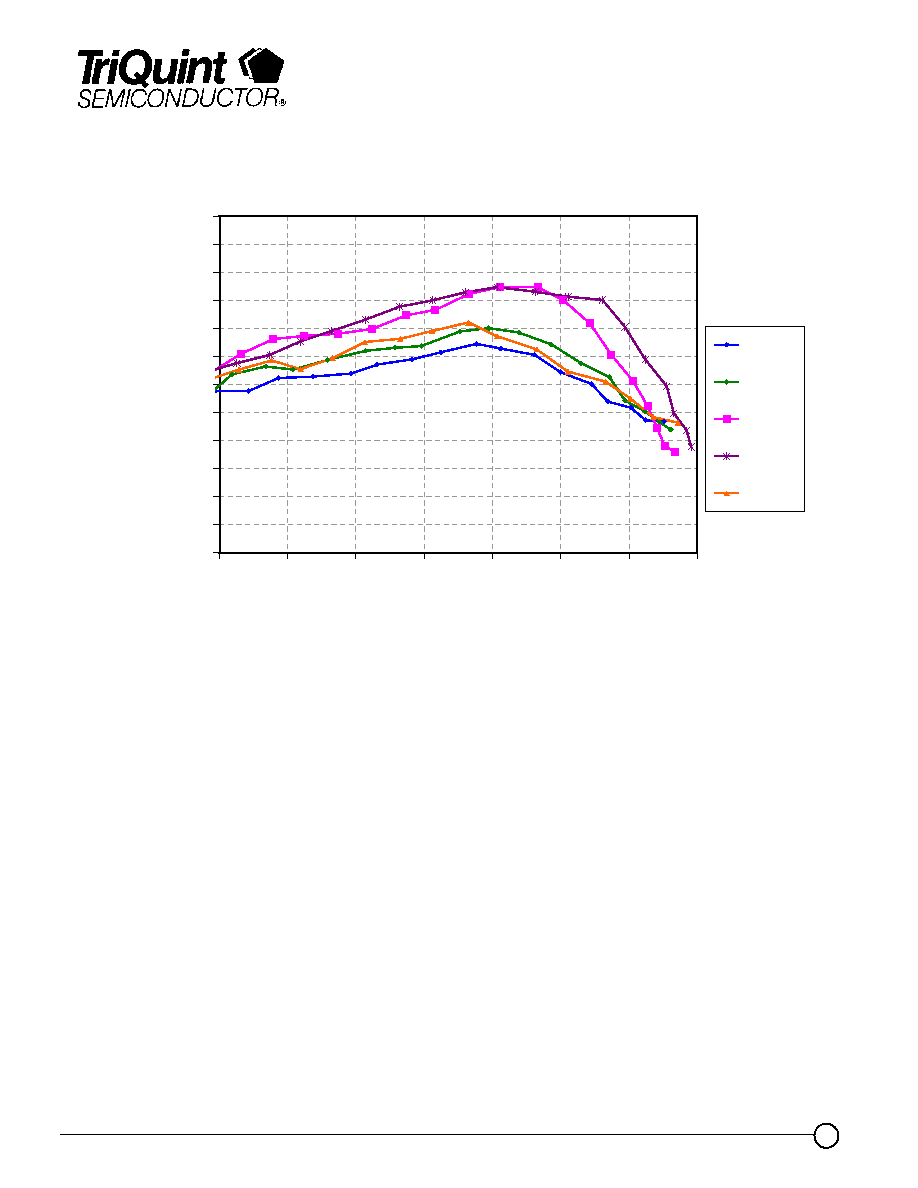
Typical Fixtured Performance
Bias Conditions: Vd = 9V, Idq = 300mA
0
5
10
15
20
25
30
35
40
45
50
9
11
13
15
17
19
21
23
25
Output Power/Tone (dBm)
IMD
3 (dB
c
)
8 GHz
9 GHz
10 GHz
11 GHz
12 GHz
13 GHz
30
31
32
33
34
35
36
37
38
39
40
8
8.5
9
9.5
10
10.5
11
11.5
12
12.5
13
Frequency (GHz)
Output TOI @ Pin =-5 dBm
Advance Product Information
November 12, 2004
8
TriQuint Semiconductor Texas Phone: (972)994-8465 Fax: (972)994-8504 Email: info-mmw@tqs.com Web: www.triquint.com
TGA2700-EPU
Typical Fixtured Performance
Bias Conditions: Vd = 9V, Idq = 300mA
28
29
30
31
32
33
34
35
36
37
38
39
40
12
14
16
18
20
22
24
26
Output Power/tone (dBm)
Output TOI (dBm)
8 GHz
9 GHz
10 GHz
11 GHz
12 GHz
Advance Product Information
November 12, 2004
9
TriQuint Semiconductor Texas Phone: (972)994-8465 Fax: (972)994-8504 Email: info-mmw@tqs.com Web: www.triquint.com
0
5
10
15
20
25
30
35
6
7
8
9
10
11
12
13
Frequency (GHz)
Pout (dB
m
)
Pin = -2 dBm
Pin = 0 dBm
Pin = 2 dBm
Pin = 4 dBm
Pin = 6 dBm
Pin = 8 dBm
Pin = 10 dBm
-30
-25
-20
-15
-10
-5
0
5
10
15
20
25
30
6
7
8
9
10
11
12
13
14
Frequency (GHz)
Gain (dB)
-30
-25
-20
-15
-10
-5
0
5
10
15
20
25
30
Re
turn Los
s
(dB)
Input
Output
Gain
TGA2700-EPU
Typical Fixtured Performance
Bias Conditions: Vd = 9V, Idq = 225mA

Advance Product Information
November 12, 2004
10
TriQuint Semiconductor Texas Phone: (972)994-8465 Fax: (972)994-8504 Email: info-mmw@tqs.com Web: www.triquint.com
TGA2700-EPU
0
5
10
15
20
25
30
35
-2
-1
0
1
2
3
4
5
6
7
8
9
10
Input Power (dBm)
Pout (dBm) & Gain (dB)
0.2
0.22
0.24
0.26
0.28
0.3
0.32
0.34
0.36
0.38
0.4
Id (A)
Id
@ 10 GHz
Output Power
Gain
@ 10 GHz
10
13
16
19
22
25
28
31
34
6
7
8
9
10
11
12
13
Frequency (GHz)
Pout @
Pin = +10dBm (dBm)
0
5
10
15
20
25
30
35
40
PAE (
%
)
Output Power
PAE
Typical Fixtured Performance
Bias Conditions: Vd = 9V, Idq = 225mA
Advance Product Information
November 12, 2004
11
TriQuint Semiconductor Texas Phone: (972)994-8465 Fax: (972)994-8504 Email: info-mmw@tqs.com Web: www.triquint.com
Typical Fixtured Performance
Bias Conditions: Vd = 9V, Idq = 225mA
TGA2700-EPU
0
5
10
15
20
25
30
35
40
45
50
9
11
13
15
17
19
21
23
25
Output Power/Tone (dBm)
IMD
3 (dB
c
)
8 GHz
9 GHz
10 GHz
11 GHz
12 GHz
13 GHz
30
31
32
33
34
35
36
8
8.5
9
9.5
10
10.5
11
11.5
12
12.5
13
Frequency (GHz)
Output TOI
@
P
i
n =-5 dBm
Advance Product Information
November 12, 2004
12
TriQuint Semiconductor Texas Phone: (972)994-8465 Fax: (972)994-8504 Email: info-mmw@tqs.com Web: www.triquint.com
Typical Fixtured Performance
Bias Conditions: Vd = 9V, Idq = 225mA
TGA2700-EPU
30
31
32
33
34
35
36
37
12
14
16
18
20
22
24
26
Output Power/tone (dBm)
Output TOI (dBm)
8 GHz
9 GHz
10 GHz
11 GHz
12 GHz

Advance Product Information
November 12, 2004
13
TriQuint Semiconductor Texas Phone: (972)994-8465 Fax: (972)994-8504 Email: info-mmw@tqs.com Web: www.triquint.com
TGA2700-EPU
Mechanical Characteristics
GaAs MMIC devices are susceptible to damage from Electrostatic Discharge. Proper precautions should
be observed during handling, assembly and test.
�
�
�
�
�
�
�
�
�
�
�
�
8QLWV PLOOLPHWHUV LQFKHV�
7KLFNQHVV �
&KLS HGJH WR ERQG SDG GLPHQVLRQV DUH VKRZQ WR FHQWHU RI ERQG SDG
&KLS VL]H WROHUDQFH �
*1' ,6 %$&.6,'( 2) 00,&
%RQG SDG
5) ,Q�
[ [ �
%RQG SDG
9G�
[ [ �
%RQG SDG
5) 2XW�
[ [ �
%RQG SDG
9J�
[ [ �

Advance Product Information
November 12, 2004
14
TriQuint Semiconductor Texas Phone: (972)994-8465 Fax: (972)994-8504 Email: info-mmw@tqs.com Web: www.triquint.com
GaAs MMIC devices are susceptible to damage from Electrostatic Discharge. Proper precautions should
be observed during handling, assembly and test.
Recommended Assembly Diagram
TGA2700-EPU
5) ,1
9G
5) 287
9J
S)
S)
X)
RKP
9J

Advance Product Information
November 12, 2004
15
TriQuint Semiconductor Texas Phone: (972)994-8465 Fax: (972)994-8504 Email: info-mmw@tqs.com Web: www.triquint.com
Assembly Process Notes
GaAs MMIC devices are susceptible to damage from Electrostatic Discharge. Proper precautions should
be observed during handling, assembly and test.
Reflow process assembly notes:
À
Use AuSn (80/20) solder with limited exposure to temperatures at or above 300
░
C for 30 sec
À
An alloy station or conveyor furnace with reducing atmosphere should be used.
À
No fluxes should be utilized.
À
Coefficient of thermal expansion matching is critical for long-term reliability.
À
Devices must be stored in a dry nitrogen atmosphere.
Component placement and adhesive attachment assembly notes:
À
Vacuum pencils and/or vacuum collets are the preferred method of pick up.
À
Air bridges must be avoided during placement.
À
The force impact is critical during auto placement.
À
Organic attachment can be used in low-power applications.
À
Curing should be done in a convection oven; proper exhaust is a safety concern.
À
Microwave or radiant curing should not be used because of differential heating.
À
Coefficient of thermal expansion matching is critical.
Interconnect process assembly notes:
À
Thermosonic ball bonding is the preferred interconnect technique.
À
Force, time, and ultrasonics are critical parameters.
À
Aluminum wire should not be used.
À
Devices with small pad sizes should be bonded with 0.0007-inch wire.
À
Maximum stage temperature is 200
░
C.
TGA2700-EPU