www.ti.com
FEATURES
APPLICATIONS
DESCRIPTION
bq27000, bq27200
SLUS556B SEPTEMBER 2004 REVISED NOVEMBER 2004
SINGLE CELL Li-Ion AND Li-Pol BATTERY GAS GAUGE IC FOR PORTABLE
APPLICATIONS (bqJUNIORTM)
·
PDA
·
HDQ (bq27000) or I
2
C (bq27200)
Communication
·
Smart Phones
·
MP3 Players
·
Reports Accurate Time-to-Empty With
Measured Load and Historical Maximum and
·
Digital Cameras
Standby Loads
·
Internet Appliances
·
Reports Temperature, Voltage, and Current
·
Handheld Devices
·
High Accuracy Charge and Discharge Current
Integration with Automatic Offset Calibration
·
Requires No User Calibration
The
bqJUNIOR
series
are
highly
accurate
stand-alone single-cell Li-Ion and Li-Pol battery ca-
·
Programmable Input/Output Port
pacity monitoring and reporting devices targeted at
·
Internal User EEPROM Configuration Memory
space-limited, portable applications. The IC monitors
·
Automatic Capacity Reduction With Age
a voltage drop across a small current sense resistor
connected in series with the battery to determine
·
Stable Oscillator Without External
charge and discharge activity of the battery. Compen-
Components
sations for battery temperature, self-discharge, and
·
Dynamic End-of-Discharge Detection Delay to
discharge
rate
are
applied
to
the
capacity
Allow Use in a High-Dynamic Load
measurments to provide available time-to-empty in-
Environment
formation across a wide range of operating con-
·
Automatic Sleep Mode When Communication
ditions. Battery capacity is automatically recalibrated,
or learned, in the course of a discharge cycle from full
Lines are Low
to empty. Internal registers include current, capacity,
·
Small 3 mm x 4 mm QFN Package
time-to-empty, state-of-charge, cell temperature and
·
Five Low-Power Operating Modes
voltage, status, and more.
Active: < 90 µA
The bqJUNIOR can operate directly from single-cell
Sleep: < 2.5 µA
Li-Ion and Li-Pol batteries and communicates to the
system over a HDQ one-wire or I
2
C serial interface.
Ship: < 2 µA (bq27000 only)
Hibernate: < 1.5 µA
Data Retention: < 20 nA
Please be aware that an important notice concerning availability, standard warranty, and use in critical applications of Texas
Instruments semiconductor products and disclaimers thereto appears at the end of this data sheet.
bqJUNIOR is a trademark of Texas Instruments.
PRODUCTION DATA information is current as of publication date.
Copyright © 2004, Texas Instruments Incorporated
Products conform to specifications per the terms of the Texas
Instruments standard warranty. Production processing does not
necessarily include testing of all parameters.
www.ti.com
TYPICAL APPLICATION
UDG-04096
+
PACK-
PACK+
HDQ
ESD Protection
D2
5.6 V
R7
100
R8
100
R1
1 k
C1
0.1
µ
F
R2
1 k
R
S
0.02
R4
10 k
C2
0.1
µ
F
C3
0.1
µ
F
C4
0.1
µ
F
C3
0.1
µ
F
R3
1 k
Li-Ion Protector
Li-Ion
or
Li-Pol
PGM TP
1
2
3
4
9
8
7
6
GPIO
SRP
SRN
BAT
RBI
VCC
VSS
D/C
bq27000DRK
5
HDQ
10
PGM
11
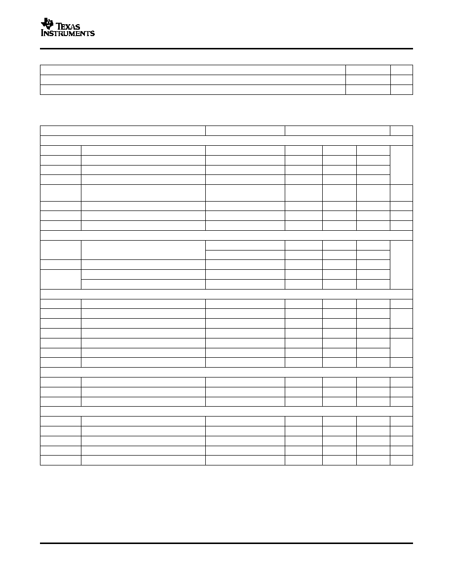
ABSOLUTE MAXIMUM RATINGS
bq27000, bq27200
SLUS556B SEPTEMBER 2004 REVISED NOVEMBER 2004
ORDERING INFORMATION
TA
COMMUNICATION INTERFACE
PACKAGED DEVICES
(1)
MARKINGS
HDQ
bq27000DRKR
27000
-20
°
C to 70
°
C
I
2
C
bq27200DRKR
27200
(1)
The DRK package is available taped and reeled only. Quantities are 2,000 devices per reel.
over operating free-air temperature range (unless otherwise noted)
bq27000
UNITS
bq27200
V
CC
Supply voltage
(with respect to V
SS
)
-0.3 to 7
-0.3 to
SRP, SRN, RBI, BAT (all with respect to V
SS
)
V
CC
+0.3
V
HDQ, SCL, SDA, GPIO (all with respect to
V
IN
Input voltage
-0.3 to 7
V
SS
)
PGM (with respect to V
SS
) during EEPROM
-0.3 to 22
programming
I
SINK
Output sink current
GPIO, SCL, SDA, HDQ
5
mA
T
A
Operating free-air temperature range
-20 to 70
T
stg
Storage temperature range
-65 to 150
°
C
T
J
Operating junction temperature range
-40 to 125
Lead temperature (soldering, 10 sec)
300
2
www.ti.com
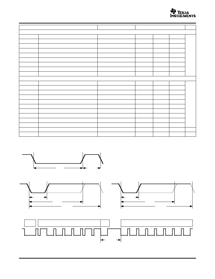
RECOMMENDED OPERATING CONDITIONS
ELECTRICAL CHARACTERISTICS
bq27000, bq27200
SLUS556B SEPTEMBER 2004 REVISED NOVEMBER 2004
MIN
MAX
UNIT
V
CC
Supply voltage
2.6
4.5
V
T
A
Operating free-air temperature
20
70
°
C
over operating free-air temperature range and supply voltage range (unless otherwise noted)
PARAMETER
TEST CONDITIONS
MIN
TYP
MAX
UNIT
GENERAL
I
CC(VCC)
Active current
52
90
I
CC(SLP)
Sleep current
1.0
2.5
µA
I
CC(SHP)
Ship current (bq27000 only)
0.9
2.0
I
CC(POR)
Hibernate current
0 < V
CC
< 1.5 V
0.6
1.5
RBI pin only, V
CC
<
RBI current
< 1
20
nA
V
CC(POR)
V
(POR)
POR threshold
2.0
2.6
V
Input impedance
BAT, SRN, SRP
10
M
Pull-down current
HDQ, SCL, SDA
2.7
4.5
µA
HDQ, SCL, SDA and GPIO
V
CC
< 4.2 V
1.7
V
IH
High-level input voltage
V
CC
> 4.2 V
1.9
V
IL
Low-level input voltage
0.7
V
Low-level output voltage (GPIO)
I
OL
= 1 mA
0.4
V
OL
Low-level output voltage (HDQ, SCL, SDA)
I
OL
= 2 mA
0.4
VOLTAGE AND TEMPERATURE MEASUREMENT
Measurement range
V
CC
= V
(BAT)
2.6
4.5
V
Reported voltage resolution
2.7
mV
Reported accuacy
-25
25
Voltage update time
2.56
s
Reported temperature resolution
0.25
°
K
Reported temperature accuracy
-3
3
Temperature update time
2.56
s
TIME, CURRENT AND CAPACITY (3.0 V
V
CC
4.2 V, 0
°
C
T
A
50
°
C)
f
OSC
Internal oscillator frequency
-2.2%
1.5%
Current gain variability
-0.5%
0.5%
Coulometric gain variability
-1.7%
0.5%
EEPROM PROGRAMMING ( V
CC
3.0 V, -20
°
C
T
A
35
°
C)
(1)
Programming voltage rise time
0.5
1.5
ms
Programming voltage high time
10
100
ms
Programming voltage fall time
0.5
1.5
ms
Programming voltage
Applied to PGM pin
20
22
V
EEPROM programming current
V
PROGRAM
= 21 V
15
mA
(1)
Maximum number of programming cycles on the EEPROM is 10 and data retention time is 10 years at T
A
= 85
°
C.
3
www.ti.com
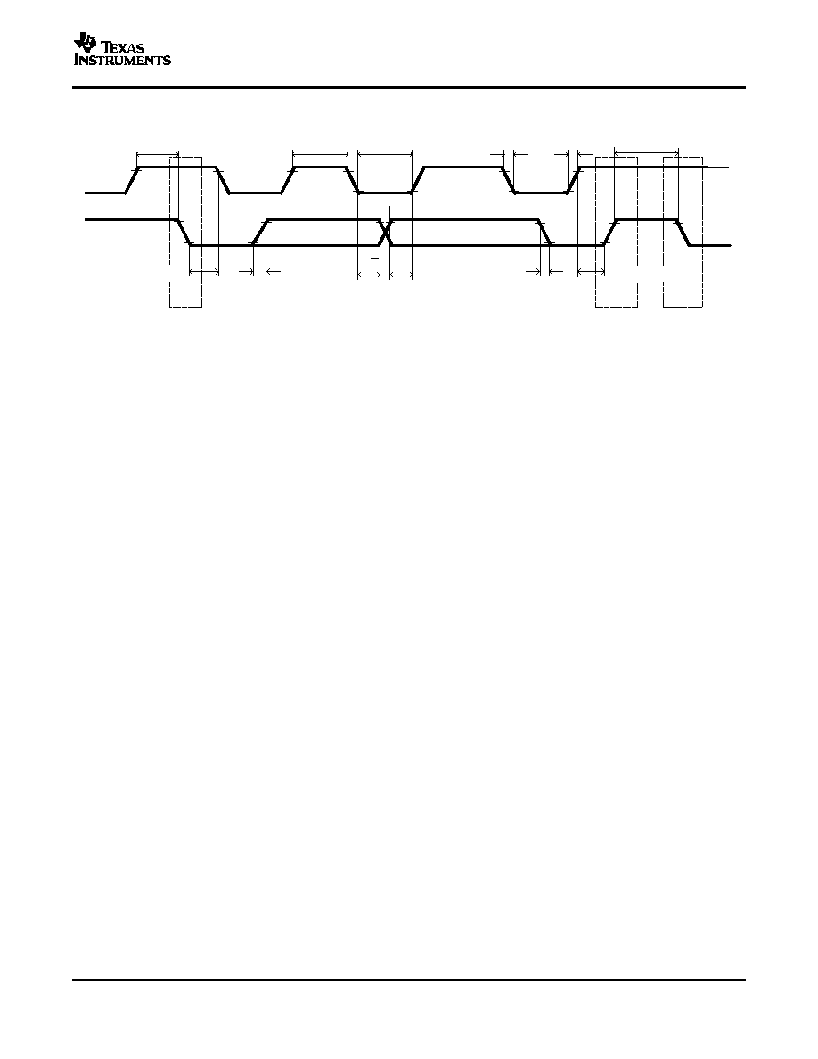
TIMING DIAGRAMS
1-Bit
R/W
UDG-03039
Break
7-Bit Address
8-Bit Data
t
(B)
t
(BR)
t
(HW1)
t
(HW0)
t
(CYCH)
t
(RSPS)
t
(CYCD)
t
(DW0)
t
(DW1)
(a) Break and Break Recovery
(b) Host Transmitted Bit
(c) bqJUNIOR Transmitted Bit
(d) bqJUNIOR to Host Response
bq27000, bq27200
SLUS556B SEPTEMBER 2004 REVISED NOVEMBER 2004
PARAMETER
TEST CONDITIONS
MIN
TYP
MAX
UNIT
STANDARD HDQ SERIAL COMMUNICATION TIMING (bq27000 only)
t
(B)
Break timing
190
t
(BR)
Break recovery
40
t
(CYCH)
Host bit window
190
t
(HW1)
Host sends 1
0.5
50
t
(HW0)
Host sends 0
86
145
µs
t
(RSPS)
bqJUNIOR to host response
190
320
t
(CYCD)
bqJUNIOR bit window
190
250
t
(DW1)
bqJUNIOR sends 1
32
50
t
(DW0)
bqJUNIOR sends 0
80
145
STANDARD I
2
C SERIAL COMMUNICATION TIMING (bq27200 only)
t
r
SCL/SDA rise time
1
t
f
SCL/SDA fall time
300
t
w(H)
SCL pulse width (high)
4
t
w(L)
SCL pulse width (low)
4.7
t
su(STA)
Setup for repeated start
4.7
µs
t
d(STA)
Start to first falling edge of SCL
4
t
su(DAT)
Data setup time
250
t
h(DAT)
Data hold time
300
t
su(STOP)
Setup time for stop
4
t
(BUF)
Bus free time between stop and start
4.7
f
(SCL)
Clock frequency
100
kHz
t
(BUSERR)
Bus error timeout
14.5
18.8
s
Figure 1. HDQ Bit Timing Diagram
4