1/10
s
2.5V OUTPUT VOLTAGE
s
ULTRA LOW CURRENT CONSUMPTION:
40
µ
A TYP.
s
HIGH PRECISION @ 25°C
±2% and ±1%
s
HIGH STABILITY WHEN USED WITH
CAPACITIVE LOAD
s
INDUSTRIAL TEMPERATURE RANGE:
-40 to +85°C
s
150ppm/°C MAXIMUM TEMPERATURE
COEFFICIENT
DESCRIPTION
The TS4040 is a low power shunt voltage refer-
ence providing a stable 2.5V output voltage over
the industrial temperature range (-40 to +85°C).
Available in SOT23-3 surface mount package, it
can be designed in applications where space sav-
ing is a critical issue.
The low operating current is a key advantage for
power restricted designs. In addition, the TS4040
is very stable and can be used in a broad range of
application conditions.
APPLICATION
s
Computers
s
Instrumentation
s
Battery chargers
s
Switch Mode Power Supply
s
Battery operated equipments
ORDER CODE
Z = TO92 Plastic package - also available in Bulk (Z), Tape & Reel (ZT)
and Ammo Pack (AP)
LT = Tiny Package (SOT23-3) - only available in Tape & Reel (LT)
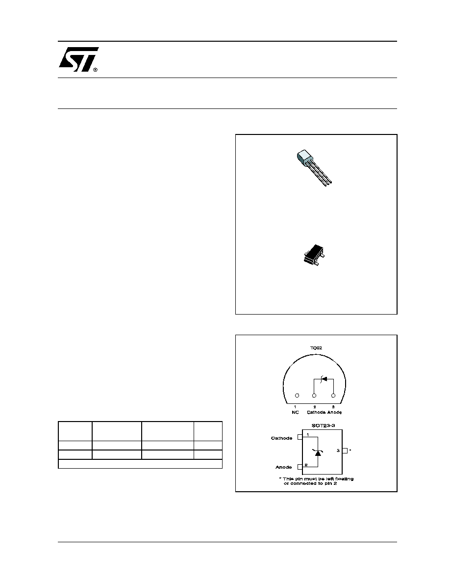
PIN CONNECTIONS (top view)
Precision
TO92
SOT23-3
SOT23
Marking
2%
TS4040EIZ-2.5 TS4040EILT-2.5
L243
1%
TS4040DIZ-2.5 TS4040DILT-2.5
L242
Single temperature range: -40 to +85°C
Z
TO92
(Plastic Package)
L
SOT23-3L
(Plastic Micropackage)
TS4040
2.5V MICROPOWER SHUNT VOLTAGE REFERENCE
March 2002
TS4040
2/10
ABSOLUTE MAXIMUM RATINGS
OPERATING CONDITIONS
Symbol
Parameter
Value
Unit
I
k
Reverse Breakdown Current
20
mA
I
f
Forward Current
10
mA
P
d
Power Dissipation
1)
SOT23-3
TO92
360
625
mW
T
std
Storage Temperature
-65 to +150
°C
ESD
Human Body Model (HBM)
2
kV
Machine Model (MM)
200
V
Tlead
Lead Temperatue (soldering, 10 seconds)
260
°C
1. Pd has been calculated with Tamb = 25°C, Tjunction =150°C andRthja = 200°C/W for the TO92 package
Rthja = 340°C/W for the SOT23-3 package
Symbol
Parameter
Value
Unit
I
kmin
Minimum Operating Current
60
µ
A
I
kmax
Maximum Operating Current
15
mA
T
oper
Operating Free Air Temperature Range
-40 to +85
°C
TS4040
3/10
ELECTRICAL CHARACTERISTICS
TS4040E (2% Precision)
Tamb = 25°C (unless otherwise specified)
ELECTRICAL CHARACTERISTICS
TS4040D (1% Precision)
Tamb = 25°C (unless otherwise specified)
Symbol
Parameter
Test Condition
Min.
Typ.
Max.
Unit
Vk
Reverse Breakdown Voltage
Ik = 100
µ
A
2.45
2.5
2.55
V
Reverse Breakdown Voltage Tolerance
Ik = 100
µ
A
-40°C < T < +85°C
-50
-74
50
74
mV
Ikmin
Minimum Operating Current
T = 25°C
40
65
µ
A
-40°C < T < +85°C
70
Vref/
T Average Temperature Coefficient
Ik = 100
µ
A
30
150
ppm/°C
Vk/
Ik
Reverse Breakdown Voltage Change
with Operating Current Range
Ikmin < Ik < 1mA
-40°C < T < +85°C
0.4
1
1.2
mV
1mA < Ik < 15mA
-40°C < T < +85°C
2.5
8
10
Rka
Reverse Static Impedance
Ik = Ikmin to 1mA
-40°C < T < +85°C
0.4
1
1.2
Ik = 1 to 15mA
-40°C < T < +85°C
0.2
0.6
0.7
Kvh
Long Term Stability
Ik = 100
µ
A, t = 1000hrs
120
ppm
En
Wide Band Noise
Ik = 100
µ
A
10Hz < f < 10kHz
35
µ
Vrms
Note: Limits are 100% production tested at 25°C. Limits over temperature are guaranteed through correlation and by design.
Symbol
Parameter
Test Condition
Min.
Typ.
Max.
Unit
Vk
Reverse Breakdown Voltage
Ik = 100
µ
A
2.475
2.5
2.525
V
Reverse Breakdown Voltage Tolerance
Ik = 100
µ
A
-40°C < T < +85°C
-25
-49
25
49
mV
Ikmin
Minimum Operating Current
T = 25°C
40
65
µ
A
-40°C < T < +85°C
70
Vref/
T Average Temperature Coefficient
Ik = 100
µ
A
30
150
ppm/°C
Vk/
Ik
Reverse Breakdown Voltage Change
with Operating Current Range
Ikmin < Ik < 1mA
-40°C < T < +85°C
0.4
1
1.2
mV
1mA < Ik < 15mA
-40°C < T < +85°C
2.5
8
10
Rka
Reverse Static Impedance
Ik = Ikmin to 1mA
-40°C < T < +85°C
0.4
1
1.2
Ik = 1mA to 15mA
-40°C < T < +85°C
0.2
0.6
0.7
Kvh
Long Term Stability
Ik = 100
µ
A, t = 1000hrs
120
ppm
En
Wide Band Noise
Ik = 100
µ
A
10Hz < f < 10kHz
35
µ
Vrms
Note: Limits are 100% production tested at 25°C. Limits over temperature are guaranteed through correlation and by design.

TS4040
4/10
Reference voltage versus cathode current
-0.5
0
0.5
1
1.5
2
2.5
Cathode voltage (V)
-5
0
5
10
15
C
a
t
h
ode c
urr
ent
(m
A
)
Test circuit
Vin
Ik=(Vin-Vref)/R
Vout=Vref
R
Static impedance (Rka) versus
temperature
-40
-20
0
20
40
60
80
Temperature (°C)
0
0.05
0.1
0.15
0.2
S
t
a
t
ic im
p
edan
ce (
O
hm
s
)
Minimum operating current
0
20
40
Cathode current (µA)
0
0.5
1
1.5
2
2.5
3
C
a
t
h
ode
vo
l
t
a
ge (
V
)
T=+85°C
T=-40°C
T=+25°C
-40
-20
0
20
40
60
80
Temperature (°C)
2.42
2.44
2.46
2.48
2.5
2.52
2.54
2.56
2.58
C
a
t
h
o
d
e
vo
lt
ag
e (
V
)
+2%
-2%
-1%
+1%
Noise voltage versus Frequency
0.1
1.0
10.0
100.0
1000.0
Frequency (KHz)
0
500
1000
1500
N
o
i
s
e v
o
l
t
age (n
V
/
V
H
z
)
C
L
=10µF
C
L
=0
C
L
=100µF
C
L
=100nF
C
L
=1µF
TS4040
5/10
Ik=100µA
Ou
t
p
u
t
25k ohm
Pulse
Generator
In
t
p
u
t
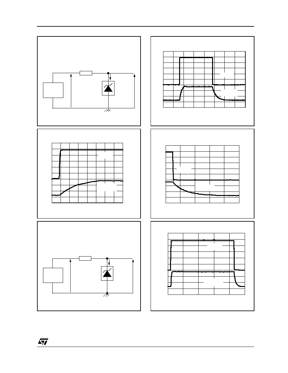
Test circuit for pulse response at Ik=100µA
Pulse response for Ik=100µA
Detailed part
0
0.5
1
1.5
2
Time (µs)
0V
5V
2.5V
0V
Input
Output
Ik=1mA
O
u
t
put
Pulse
Generator
I
n
t
put
Test circuit for pulse response at Ik=1mA
2.5k ohm
Pulse response for Ik=100µA
0
5
0
2.5
0
5
10
15
20
Time (µs)
Input
Output
Pulse response for Ik=100µA
Detailed part
0
1
2
3
4
5
Time (µs)
0V
5V
0V
2.5V
Input
Output
Pulse response for Ik=1mA
0V
5V
0V
2.5V
0
1
2
3
4
5
Time (µs)
Input
Output