STPC
®
ELITE
X86 Core General Purpose PC Compatible System - on - Chip
Release 1.3 - January 29, 2002
1/87
This is preliminary information on a new product now in development or undergoing evaluation. Details are subject to change without notice.
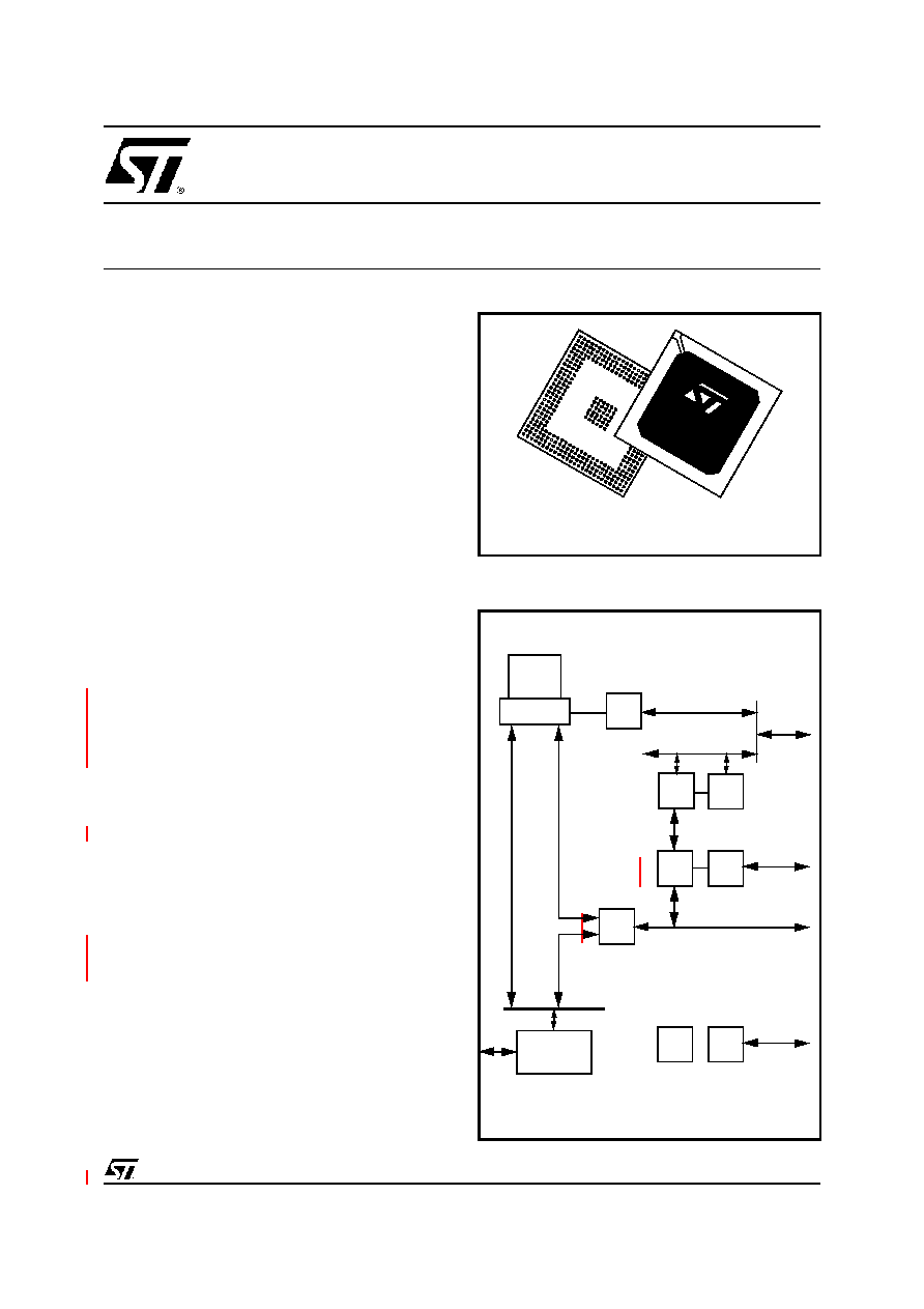
Logic Diagram
s
POWERFUL X86 PROCESSOR
s
64-BIT SDRAM CONTROLLER AT 100MHz
s
INTEGRATED PCI NORTH / SOUTH
BRIDGE CONTROLLER
s
ISA MASTER / SLAVE / DMA
s
16-BIT LOCAL BUS INTERFACE FOR LOW
COST AND EMBEDDED APPLICATIONS
s
EIDE CONTROLLER
s
INTEGRATED PERIPHERAL CONTROLLER
- DMA CONTROLLER
- INTERRUPT CONTROLLER
- TIMER / COUNTERS
s
POWER MANAGEMENT UNIT
s
I˛C INTERFACE
s
16 ENHANCED GENERAL PURPOSE I/Os.
s
JTAG IEEE1149.1
s
PROGRAMMABLE OUTPUT CLOCK UP TO
135MHz
s
COMMERCIAL AND INDUSTRIAL TEM-
PERATURE RANGES
DESCRIPTION
The STPC Elite integrates a fully static x86
processor up to 133 MHz, fully compatible with
standard x86 processors, and combines it with
powerful chipset to provide a general purpose PC
compatible subsystem on a single device. The
device is packaged in a 388 Ball Grid Array
(PBGA).
The STPC Elite has a low voltage operation with
V
CORE
= 2.5V and has 5V tolerant I/Os (3.3V
output levels).
PBGA388
ST
PC
EL
ITE
x86
Core
Host I/F
SDRAM
CONTROL
PCI
I/F
PCI
ISA
I/F
EIDE
ctrl
PCI
I/F
ISA BUS
EIDE
L.B.
I/F
LOCAL BUS
IPC
JTAG
PMU

2/87
Release 1.3 - January 29, 2002
This is preliminary information on a new product now in development or undergoing evaluation. Details are subject to change without notice.
s
X86 Processor core
s
Fully static 32-bit 5-stage pipeline, x86
processor fully PC compatible.
s
Can access up to 4GB of external memory.
s
8KByte unified instruction and data cache
with write back and write through capability.
s
Parallel processing integral floating point unit,
with automatic power down.
s
Clock core speeds up to of 100 MHz in x1
clock mode and 133MHz in x2 mode.
s
Fully static design for dynamic clock control.
s
Low power and system management modes.
s
SDRAM Controller
s
64-bit data bus.
s
Up to 100MHz SDRAM clock speed.
s
Supports up to 128 MB system memory.
s
Supports 16-, 64- and 128-Mbit memories.
s
Supports up to 4 memory banks.
s
Supports buffered, non buffered, registered
DIMMs
s
4-line write buffers for CPU to DRAM and PCI
to DRAM cycles.
s
4-line read prefetch buffers for PCI masters.
s
Programmable latency
s
Programmable timing for DRAM parameters.
s
Supports -8, -10, -12, -13, -15 memory parts
s
Supports memory hole between 1MB and
8MB for PCI/ISA busses.
s
PCI Controller
s
Compliant with PCI 2.1 specification.
s
Integrated PCI arbitration interface. Up to 3
masters can connect directly. External logic
allows for greater than 3 masters.
s
Translation of PCI cycles to ISA bus.
s
Translation of ISA master initiated cycle to
PCI.
s
Support for burst read/write from PCI master.
s
0.25X, 0.33X and 0.5X Host clock PCI clock.
s
ISA master/slave
s
Generates the ISA clock from either
14.318MHz oscillator clock or PCI clock
s
Supports programmable extra wait state for
ISA cycles
s
Supports I/O recovery time for back to back
I/O cycles.
s
Fast Gate A20 and Fast reset.
s
Supports the single ROM that C, D, or E.
blocks shares with F block BIOS ROM.
s
Supports flash ROM.
s
Supports ISA hidden refresh.
s
Buffered DMA & ISA master cycles to reduce
bandwidth utilization of the PCI and Host
bus. NSP compliant.
s
16-bit I/O decoding.
s
Local Bus interface
s
Multiplexed with ISA/DMA/Timer functions.
s
High speed, low latency bus.
s
Supports 32-bit Flash burst.
s
16-bit data bus with word steering capability.
s
Separate memory and I/O address spaces.
s
Programmable timing (Host clock granularity)
s
Supports 2 cachable banks of 16MB flash
devices with boot block shadowed to
0x000F0000.
s
2 Programmable Flash/EPROM Chip Select.
s
4 Programmable I/O Chip Select.
s
2-level hardware key protection for Flash boot
block protection.
s
24 bit address bus.
s
EIDE Controller
s
Compatible with EIDE (ATA-2).
s
Backward compatibility with IDE (ATA-1).
s
Supports up to 4 IDE devices
s
Supports PIO and Bus Master IDE
s
Concurrent channel operation (PIO & DMA
modes) - 4 x 32-Bit Buffer FIFO per channel
s
Support for 11.1/16.6 MB/s, I/O Channel
Ready PIO data transfers.
s
Bus Master with scatter/gather capability.
s
Multi-word DMA support for fast IDE drives.
s
Individual drive timing for all four IDE devices.
s
Supports both legacy & native IDE modes.
s
Supports hard drives larger than 528MB.
s
Support for CD-ROM and tape peripherals.
s
Integrated Peripheral Controller
s
2X8237/AT compatible 7-channel DMA
controller.
s
2X8259/AT compatible interrupt Controller.
16 interrupt inputs - ISA and PCI.
s
Three 8254 compatible Timer/Counters.
s
Co-processor error support logic.
s
Supports external RTC.
s
Power Management
s
Four power saving modes: On, Doze,
Standby, Suspend.

GENERAL DESCRIPTION
Release 1.3 - January 29, 2002
5/87
This is preliminary information on a new product now in development or undergoing evaluation. Details are subject to change without notice.
1. GENERAL DESCRIPTION
At the heart of the STPC Elite is an advanced
processor block that includes a powerful x86
processor core along with a 64-bit SDRAM
controller, a high speed PCI local-bus controller
and Industry standard PC chip set functions
(Interrupt controller, DMA Controller, Interval timer
and ISA bus) and EIDE controller.
The processor bus runs at the speed of the
processor (x1 mode) or half the speed (x2 mode).
The STMicroelectronics x86 processor core is
embedded with standard and application specific
peripheral modules on the same silicon die. The
core has all the functionality of the ST standard
x86 processor products, including the low power
System Management Mode (SMM).
System Management Mode (SMM) provides an
additional interrupt and address space that can be
used for system power management or software
transparent emulation of peripherals. While
running in isolated SMM address space, the SMM
interrupt routine can execute without interfering
with the operating system or application
programs.
The `standard' PC chipset functions (DMA,
interrupt controller, timers, power management
logic) are integrated with the x86 processor core.
The PCI bus is the main data communication link
to the STPC Elite chip. The STPC Elite translates
appropriate host bus I/O and Memory cycles onto
the PCI bus. It also supports generation of
Configuration cycles on the PCI bus. The STPC
Elite, as a PCI bus agent (host bridge class), fully
complies with PCI specification 2.1. The chip-set
also implements the PCI mandatory header
registers in Type 0 PCI configuration space for
easy porting of PCI aware system BIOS. The
device contains a PCI arbitration function for three
external PCI devices.
The STPC Elite integrates an ISA bus controller.
Peripheral modules such as parallel and serial
communications ports, keyboard controllers and
additional ISA devices can be accessed by the
STPC Elite chip set through this bus.
An industry standard EIDE (ATA 2) controller is
built in to the STPC Elite and connected internally
via the PCI bus.
1.1. MEMORY CONTROLLER
The STPC handles the memory data (DATA) bus
directly, controlling from 8 to 128 MBytes. The
SDRAM controller supports accesses to the
Memory Banks to/from the CPU (via the host).
Parity is not supported.
The SDRAM controller only supports 64 bit wide
Memory Banks.
Four Memory Banks (if DIMMS are used; Single
sided or two double-sided DIMMs) are supported
in the following configurations (see
Table 1-1
)
The SDRAM Controller supports buffered or
unbuffered SDRAM but not EDO or FPM modes.
SDRAMs must support Full Page Mode Type
access.
The STPC Memory Controller provides various
programmable SDRAM parameters to allow the
SDRAM interface to be optimized for different
processor bus speeds SDRAM speed grades and
CAS Latency.
1.2. POWER MANAGEMENT
The STPC Elite core is compliant with the
Advanced Power Management (APM)
specification to provide a standard method by
which the BIOS can control the power used by
personal computers. The Power Management
Unit (PMU) module controls the power
consumption, providing a comprehensive set of
features that controls the power usage and
supports compliance with the United States
Environmental Protection Agency's Energy Star
Computer Program. The PMU provides the
following hardware structures to assist the
software in managing the system power
consumption:
- System Activity Detection.
Table 1-1. Memory configurations
Memory
Bank size
Number
Organisa
tion
Device
Size
1Mx64
4
1Mx16
16Mbits
2Mx64
8
2Mx8
4Mx64
16
4Mx4
4Mx64
4
2Mx16x2
64Mbits
8Mx64
8
4Mx8x2
16Mx64
16
8Mx4x2
4Mx64
4
1Mx16x4
8Mx64
8
2Mx8x4
32Mx64
16
4Mx4x4
16Mx64
8
2Mx16x2
128Mbits
32Mx64
16
4Mx8x4