STATEK CORPORATION 512 N. MAIN ST., ORANGE, CA 92868 714-639-7810 FAX: 714-997-1256 www.statek.com
10154 - Rev A
DESCRIPTION
The LSM oscillator has the highest accuracy, stability and
the lowest current of all STATEK surface mount
oscillators. The design consists of a STATEK crystal, and
a CMOS-compatible integrated circuit. The hybrid design
is hermetically-sealed with a kovar lid in a surface mount
ceramic package. Permanent precision tuning of the
oscillator is accomplished by laser trimming the crystal.
FEATURES
Low power consumption
Low aging
CMOS compatible
Hermetically sealed package
Full military testing available
3 Volt operation available
APPLICATIONS
Industrial, Computer & Communications
General purpose clock oscillator
Data logger
Remote sensor
Medical test and diagnostics
Military
Portable field communication
Military high speed modem
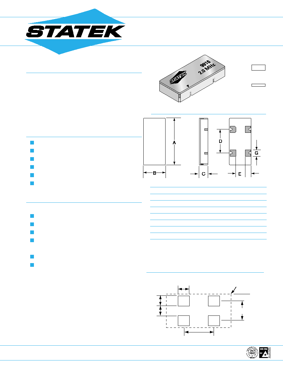
LSM OSCILLATOR
700 kHz to 2.1 MHz
Low Power Surface Mount Crystal Oscillator
3
4
2
1
F
TYP.
MAX.
DIM
INCHES
mm
INCHES
mm
A
.400
10.16
.405
10.29
B
.180
4.57
.185
4.70
C*
.071
1.80
.079
2.00
D
.200
5.08
.205
5.21
E
.080
2.03
.085
2.16
F
.050
1.27
.058
1.47
G
.055
1.40
.063
1.60
PACKAGE DIMENSIONS
SUGGESTED LAND PATTERN
.075 [1.91]
.068 [1.73]
.064 [1.63]
GRID
PLACEMENT
COURTYARD
.200 [5.08]
.132 [3.35]
actual size
side view
Termination material is Au over Ni (SM1), solder dip
(SM3) also available.
*SM1 Termination; SM3 = .084 in. (2.13mm) Max.
INCHES[mm]
TM
STATEK CORPORATION 512 N. MAIN ST., ORANGE, CA 92868 714-639-7810 FAX: 714-997-1256 www.statek.com
SPECIFICATIONS: LSM 2.0 MHz****
Specifications are typical at 25oC unless otherwise noted.
Specifications are subject to change without notice.
Supply Voltage*
5V 10% (3.3V available)
Calibration Tolerance**
A: 0.01% (100ppm)
B: 0.03%
C: 0.1%
Frequency Stability***
0
O
C to +70
O
C
0.12%
Typ.
0.017% MAX.
Voltage Coefficient
5 ppm/V MAX.
Aging
10 ppm/year MAX.
Shock
750g, 0.3msec.,1/2 sine
Vibration
10g rms, 10 - 2000 Hz
Frequency Change vs
10%Output Load Change
1 ppm MAX.
Operating Temperature -10
O
C to +70
O
C Commercial
-40
O
C to +85
O
C Industrial
-55
O
C to +125
O
C Military
* Contact the factory for lower voltage.
** Tighter tolerances available.
*** Does not include calibration tolerance. Positive variations are much smaller.
**** Contact the factory for other frequencies.
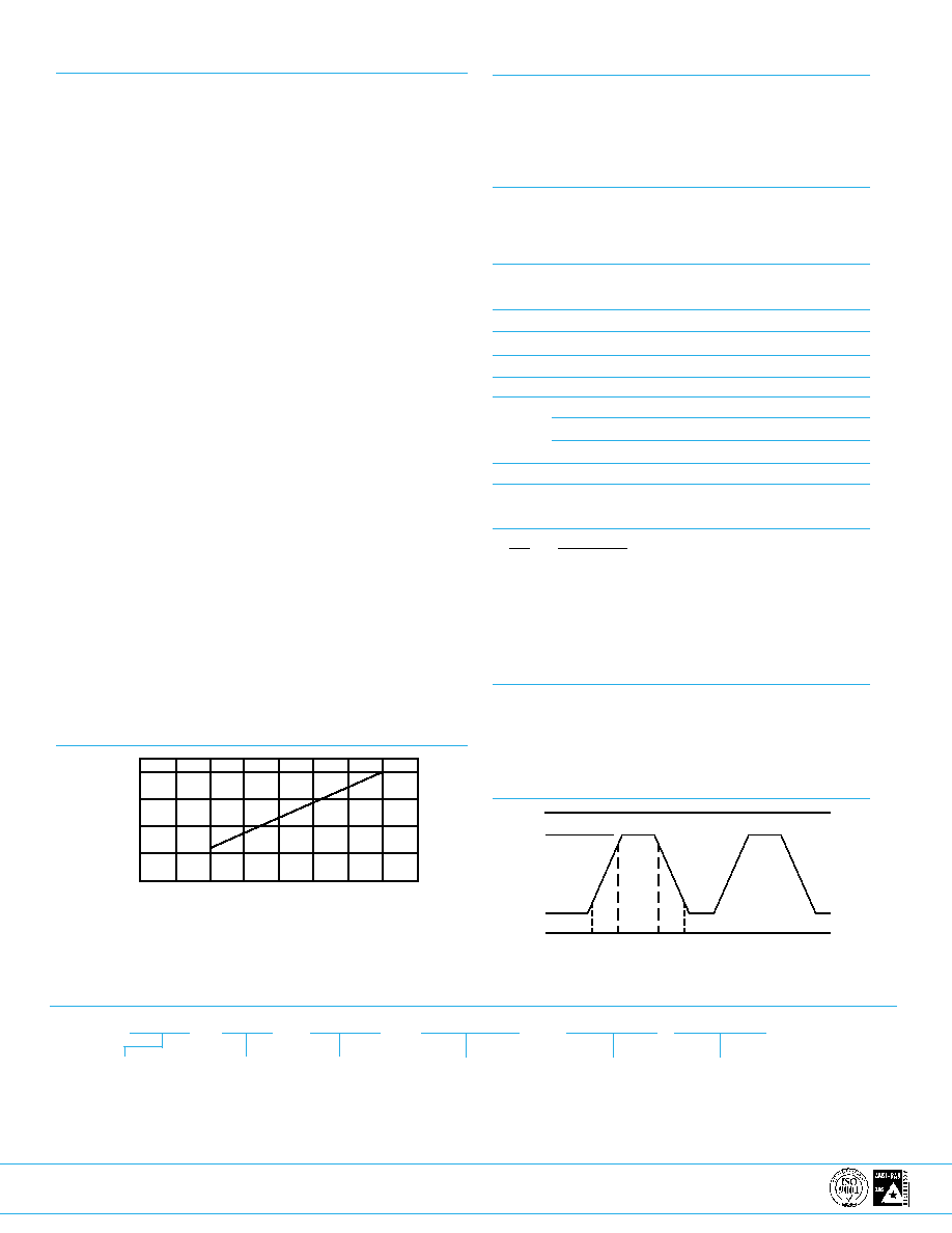
TYPICAL CURRENT CONSUMPTION,
LSM 2.0 MHZ
+
_
+
_
+
_
_
_
+
_
+
_
+
_
+
_
10154 - Rev A
ABSOLUTE MAXIMUM RATINGS
Supply Voltage V
DD
3.3V to 7V
Storage Temperature
-55
O
C to +125
O
C
Process Temperature
260
O
C 20 sec.
ELECTRICAL CHARACTERISTICS
LSM 2.0 MHz
All parameters are measured at ambient temperature
with a 10M
and 10pF load at 5V.
SYMBOL PARAMETER
MIN.
TYP.
MAX. UNIT
V
Output Voltage Hi
4.8
4.95
V
V
Output Voltage Lo
0.05
0.2
V
t
r
Rise Time (10%-90%)
12
25
nsec.
t
f
Fall Time (10%-90%)
12
25
nsec.
SYM
Duty Cycle
40
50
60
%
Supply Current
V
DD
=5V
300
400
A
V
DD
=3.3V
200
300
A
Start-Up Time
20
msec.
PIN CONNECTIONS
Pin
Connection
1
NC
2
Ground
3
Output
4
V
DD
PACKAGING
LSM
-Tray Pack (Standard)
-16mm tape, 7" or 13" reels (Optional)
Per EIA 481 (see data sheet 10109)
OUTPUT WAVE FORM
OH
OL
V
DD
V
OH
t
r
t
f
0
V
OL
90%*
10%*
* Of
V
DD
I
DD
HOW TO ORDER LSM CRYSTAL OSCILLATORS
LSM
3
S
SM3
2.0 MHz
(
A
/
I
)
Frequency
3=3.3V
Blank=5V (Std.)
"S" if special
or custom
design.
Blank if Std.
Blank= SM1 (Std.)
*Calibration
Tolerance
@ 25
O
C
(A)
(B)
(C)
Temp. Range:
C = Commercial
I = Industrial
M = Military
S = Specify
0
2
4
6
8
200
300
V
DD
(V)
CURRENT (uA)
400
100
* Other calibration fill in ppm.