Skyworks Solutions, Inc. [978] 241-7000
· Fax [978] 241-7906 · Email sales@skyworksinc.com · www.skyworksinc.com
1
Specifications subject to change without notice. 3/98A
GaAs IC Receive Diversity
T/R Switch DC2 GHz
Features
PDC Antenna Switch
Transmit to Main Antenna
Receive from Dual Antenna Ports
Operates with Positive or Differential
Voltages
Low DC Power Consumption
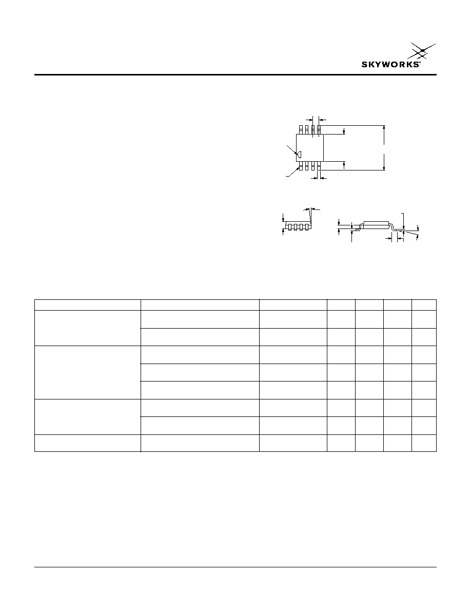
MSOP-8
AS143-59
Description
The AS143-59 is an IC FET T/R switch with receive
diversity, ideal for use in PDC handsets and low power
base stations. It can be operated with positive 3 V or
differential voltage control for high linearity. The switch is
packaged in a low cost, miniature MSOP-8 package.
On Path
Parameter
1
Frequency
2
Min.
Typ.
Max.
Unit
T
X
to M-Antenna
Insertion Loss
3
DC1.0 GHz
0.35
0.5
dB
DC2.0 GHz
0.50
0.7
dB
R
X
to M-Ant. Iso.
DC1.0 GHz
23
26
dB
DC2.0 GHz
15
19
dB
R
X
to M-Antenna
Insertion Loss
DC1.0 GHz
0.65
0.8
dB
DC2.0 GHz
0.9
1.1
dB
T
X
to M-Ant. Iso.
DC1.0 GHz
15
18
dB
DC2.0 GHz
9
12
dB
R
X
to S-Ant. Iso.
DC1.0 GHz
20
23
dB
DC2.0 GHz
12
15
dB
R
X
to S-Antenna
Insertion Loss
DC1.0 GHz
0.5
0.6
dB
DC2.0 GHz
0.9
1.1
dB
T
X
to M-Ant. Iso.
DC1.0 GHz
20
24
dB
DC2.0 GHz
12
15
dB
VSWR
4
DC1.0 GHz
1.5:1
DC2.0 GHz
1.7:1
Electrical Specifications at 25°C (-2.75, +2.75 V)
0.012 (0.30 mm)
PIN 1
PIN 1
INDICATOR
+ 0.006 (0.15 mm)
7.0°
TYP.
0.038 (0.95 mm)
0.030 (0.75 mm)
0.017
(0.43 mm)
8.0°
MAX.
0.028 (0.70 mm)
0.016 (0.40 mm)
0.007 (0.18 mm)
± 0.005 (0.12 mm)
0.006 (0.15 mm)
0.002 (0.05 mm)
- 0.002 (0.05 mm)
0.0256 (0.65 mm) TYP.
0.118 (3.00 mm)
± 0.004 (0.1 mm)
SQ.
0.193 (4.90 mm)
REF.
1. All measurements made in a 50 ohm system, unless otherwise specified.
2. DC = 300 kHz.
3. Insertion loss changes by 0.003 dB/°C.
4. Insertion loss state.

GaAs IC Receive Diversity T/R Switch DC2 GHz
AS143-59
2
Skyworks Solutions, Inc. [978] 241-7000
· Fax [978] 241-7906 · Email sales@skyworksinc.com · www.skyworksinc.com
Specifications subject to change without notice. 3/98A
Frequency (GHz)
1.4
1.2
1.0
0.8
0.6
0.4
0.2
0
0
0.5
1.5
0.75
0.25
1.0
1.25
1.75 2.0
Insertion Loss vs. Frequency
dB
R
X
to
M-Ant.
R
X
to
S-Ant.
T
X
to
M-Ant.
Frequency (GHz)
0
0.5
1.0
1.5
2.0
40
30
20
10
0
R
X
to M-Ant. Isolation vs. Frequency
dB
On Path:
T
X
to
M-Ant.
Frequency (GHz)
0
0.5
1.0
1.5
2.0
T
X
to M-Ant. and R
X
to S-Ant.
Isolation vs. Frequency
dB
On Path:
R
X
to
M-Ant.
50
40
30
20
10
0
Tx to M-Ant.
Rx to S-Ant.
Frequency (GHz)
0
0.5
1.0
1.5
2.0
40
30
20
10
0
R
X
to M-Ant. Isolation vs. Frequency
dB
On Path:
R
X
to
S-Ant.
Typical Performance Data (-2.75, +2.75 V)
Parameter
1
Condition
Frequency
Min.
Typ.
Max.
Unit
Switching Characteristics
Rise, Fall Time
75
ns
On, Off Time
150
ns
Input Power for 1 dB Compression
T
X
to M-Ant
0.9 GHz
+36
dBm
R
X
to M-Ant.
+33
dBm
R
X
to S-Ant.
+33
dBm
Intermodulation Intercept Point
For Two-tone Input Power at +13 dBm
0.9 GHz
T
X
to M-Ant.
+49
dBm
R
X
to M-Ant.
+48
dBm
Adjacent Channel Power Performance
T
X
to M-Ant (PDC Standard,
30 dBm Input, 100 kHz Detune)
+69
dBm
Harmonic Channel Power Performance
30 dBm Input
0.9 GHz
2nd Harmonic
+67
dBc
3rd Harmonic
+82
dBc
Control Voltages
V
Low
= -2.8 V
V
Low
-6.0 V
V
High
= -0.2 V
V
High
+5.0 V
Differential = +2.6 V
(V
High
V
Low
)
+10 V
1. All measurements made in a 50 ohm system, unless otherwise specified.
Operating Characteristics at 25°C (-2.75, +2.75 V)

Skyworks Solutions, Inc. [978] 241-7000
· Fax [978] 241-7906 · Email sales@skyworksinc.com · www.skyworksinc.com
3
Specifications subject to change without notice. 3/98A
GaAs IC Receive Diversity T/R Switch DC2 GHz
AS143-59
Characteristic
Value
RF Input Power
6 W > 500 MHz, 0/-10 V
Positive Voltage Differential Bias
3 V
(V
High
V
Low
)
10 V
Operating Temperature
-40°C to +85°C
Storage Temperature
-65°C to +150°C
JC
25°C/W
Absolute Maximum Ratings
Note: Exceeding these parameters may cause irreversible damage.
C
BL
R
X
T
X
V
3
V
2
V
1
GND
S-Ant.
M-Ant.
12
3
4
87
6
5
C
BL
C
BL
C
BL
V
1
V
2
V
3
T
X
M-Ant. R
X
M-Ant. R
X
S-Ant.
V
High
V
Low
V
Low
Insertion
Isolation
Isolation
Loss
V
Low
V
High
V
Low
Isolation
Insertion
Isolation
Loss
V
Low
V
Low
V
High
Isolation
Isolation
Insertion
Loss
Truth Table
Pin Out
V
Low
= -2.8 to -6 V
V
High
= -0.2 to +3.0 V
External DC blocking capacitor (C
BL
) required on all RF ports
only if V
High
> 0 V.
C
BL
= 100 pF for operation >500 MHz.