Skyworks Solutions, Inc. [978] 241-7000
·
Fax [978] 241-7906
·
Email sales@skyworksinc.com
·
www.skyworksinc.com
1
Specifications subject to change without notice. 3/02A
24.532 GHz GaAs MMIC
Sub-Harmonic Up/Down Converter Mixer
Features
Low Conversion Loss, 10 dB
High 2LO to RF Isolation, 50 dB
High LO to IF Isolation, 30 dB
Final Production Size (1.6 mm x 0.95 mm)
No DC Bias Required
Ideal for Point to Point, Point to Multi-point
and SatCom Applications
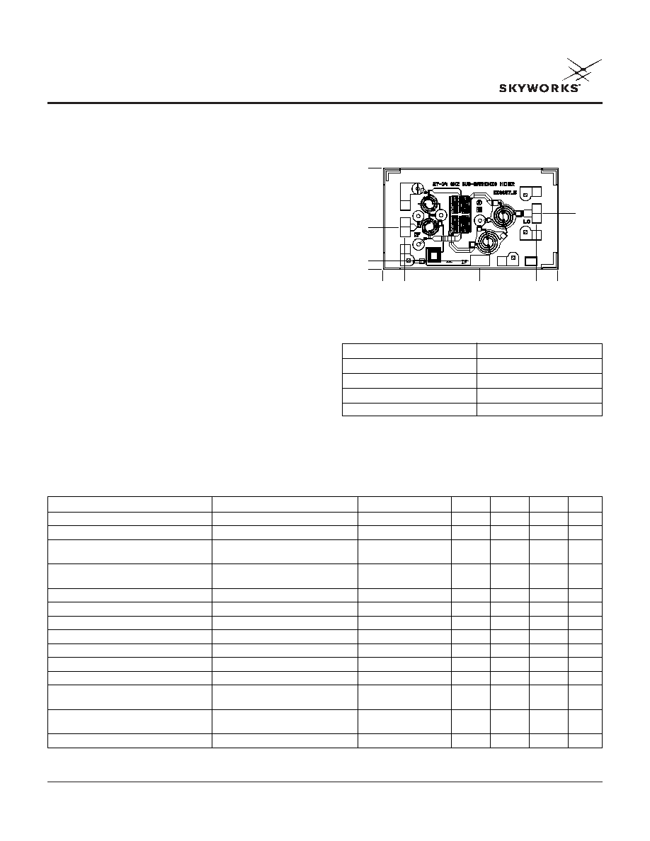
Chip Outline
AM026H1-00
Description
Alpha's double balanced sub-harmonic mixer IC has a
typical conversion loss of 10 dB at an LO power of 15 dBm
over the band 2632 GHz. The chip uses Alpha's proven
Schottky diode technology and is based upon MBE layers
for the highest uniformity and repeatability. The diodes
employ surface passivation to ensure a rugged, reliable
part with through-substrate via holes and gold-based
backside metallization to facilitate an epoxy or solder die
attach process. All chips are screened for DC diode
parameters and lot samples are RF measured to
guarantee performance.
Parameter
Condition
Symbol
Min.
Typ.
2
Max.
Unit
IF Frequency Range
F
IF
0.5
4
GHz
LO Power Level
P
LO
12
15
dBm
Conversion Loss
1
F
RF
= 24.526.5 GHz,
L
C
11.5
dB
(Up and Down Conversion)
F
LO
= 1113 GHz
Conversion Loss
1
F
RF
= 2632 GHz,
L
C
10
dB
(Up and Down Conversion)
F
LO
= 1216 GHz
LO Return Loss
1
F
LO
= 1113 GHz
RL
LO
12
dB
LO Return Loss
1
F
LO
= 1216 GHz
RL
LO
9
dB
RF Return Loss
1
F
RF
= 24.532 GHz
RL
RF
9
dB
LO to RF Isolation
1
F
LO
= 1116 GHz
ISO
LO-RF
25
dB
2LO to RF Isolation
1
2F
LO
= 2232 GHz
ISO
2LO-RF
50
dB
LO to IF Isolation
1
F
LO
= 1113 GHz
ISO
LO-IF
25
dB
LO to IF Isolation
1
F
LO
= 1216 GHz
ISO
LO-IF
30
RF Input 1 dB Compression Point
1
F
RF
= 24.532 GHz,
P
1 dB
7
F
LO
= 1116 GHz
IP3 (Input)
F
RF
= 28 GHz, F
LO
= 13.5 GHz
IP3
16
dBm
P
LO
= 15 dBm, Two-tone = 10 dBm
Four Parallel Diode Series Resistance
R
S
0.75
Electrical Specifications at 25°C
1. Not measured on a 100% basis.
2. Typical represents the median parameter value across the specified
frequency range for the median chip.
0.000
0.000
0.434
0.225
0.994
0.576
1.800
1.040
1.578
0.090
Characteristic
Value
Operating Temperature
-55°C to +125°C
Storage Temperature
-65°C to +150°C
Total Input Power (RF + LO)
23 dBm
ESD Level Per ANSI
TBD
Absolute Maximum Ratings
Preliminary

24.532 GHz GaAs MMIC Sub-Harmonic Up/Down Converter Mixer
AM026H1-00
2
Skyworks Solutions, Inc. [978] 241-7000
·
Fax [978] 241-7906
·
Email sales@skyworksinc.com
·
www.skyworksinc.com
Specifications subject to change without notice. 3/02A
Conversion Loss vs. RF Frequency
(Down Converter)
F
LO
= (F
RF
- 1 GHz)/2, P
RF
= -10 dBm
RF Frequency (GHz)
Conversion Loss (dB)
7
9
11
13
15
17
24
25
26
27
28
29
30
31
32
33
34
P
LO
= 15 dBm
P
LO
= 12 dBm
Conversion Loss vs. RF Frequency
(Up Converter)
F
LO
= (F
RF
- 1 GHz)/2, P
IF
= -10 dBm
RF Frequency (GHz)
Conversion Loss (dB)
7
9
11
13
15
17
24
25
26
27
28
29
30
31
32
33
34
P
LO
= 15 dBm
P
LO
= 12 dBm
Isolation vs. LO Frequency
P
LO
= 12 dBm
LO Frequency (GHz)
Isolation (dB)
15
20
25
30
35
40
45
11.5
12.5
13.5
14.5
15.5
16.5
LO to IF Isolation
LO to RF Isolation
2LO to RF Isolation
P
LO
= 12 dBm
2LO Frequency (GHz)
2LO to RF Isolation (dB)
30
35
40
45
50
55
60
24
25
26
27
28
29
30
31
32
33
34
RF Return Loss vs. RF Frequency
P
LO
= 12 dBm, F
LO
= 14 GHz
RF Frequency (GHz)
RF Return Loss (dB)
4
6
8
10
12
14
24
25
26
27
28
29
30
31
32
33
34
LO Return Loss vs. LO Frequency
P
LO
= 12 dBm
LO Frequency (GHz)
LO Return Loss (dB)
4
6
8
10
12
14
11.5
12.5
13.5
14.5
15.5
16.5
Typical Performance Data

24.532 GHz GaAs MMIC Sub-Harmonic Up/Down Converter Mixer
AM026H1-00
Skyworks Solutions, Inc. [978] 241-7000
·
Fax [978] 241-7906
·
Email sales@skyworksinc.com
·
www.skyworksinc.com
3
Specifications subject to change without notice. 3/02A
IF Return Loss vs. IF Frequency
F
LO
= 14 GHz, P
LO
= 12 dBm
IF Frequency (GHz)
IF Return Loss (dB)
0
1
2
3
4
5
6
7
8
9
10
5
10
15
20
25
30
35
Converson Loss vs. IF Frequency
F
LO
= 12 GHz, F
RF
= (2 * F
LO
) + F
IF
,
P
RF
= -10 dBm, P
LO
= 12 dBm
IF Frequency (GHz)
Conversion Loss (dB)
1
2
3
4
5
6
7
17
7
9
11
13
15
Compression vs. RF Power
F
RF
= 28 GHz, F
LO
= 13.5 GHz, F
IF
= 1 GHz
RF Power (dBm)
Compression (dB)
-0.5
0
0.5
1.0
1.5
-10 -8 -6 -4 -2
0
2
4
6
8 10 12 14
P
LO
= 15 dBm
P
LO
= 12 dBm
P
LO
= 18 dBm
Input P
1 dB
vs. LO Power
F
LO
= 13.5 GHz, F
RF
= 28 GHz, F
IF
= 1 GHz
LO Power (dBm)
Input P
1 dB
(dBm)
0
9
10
11
12
13
14
15
16
17
18
2
4
6
8
10
12
Conversion Loss vs. LO Power
F
RF
= 28 GHz, F
LO
= 13.5 GHz, P
RF
= -10 dBm
LO Power (dBm)
Converson Loss (dB)
Return Loss & Isolation (dB)
6
8
10
12
14
16
6
8
10
12
14
16
18
0
10
20
30
40
50
Conversion Loss
LO Return Loss
LO to IF Isolation
IF
RF
LO
RF
Balun
LO
Balun
Circuit Schematic
24.532 GHz GaAs MMIC Sub-Harmonic Up/Down Converter Mixer
AM026H1-00
4
Skyworks Solutions, Inc. [978] 241-7000
·
Fax [978] 241-7906
·
Email sales@skyworksinc.com
·
www.skyworksinc.com
Specifications subject to change without notice. 3/02A
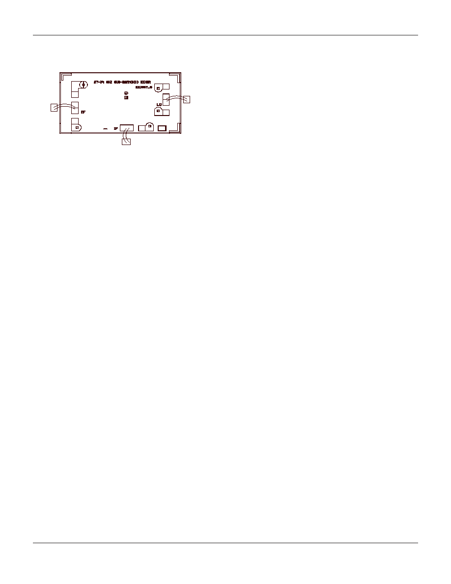
Wire Bonding Configurations
IF
RF
LO