Semiconductor Group
1
1998-08-27
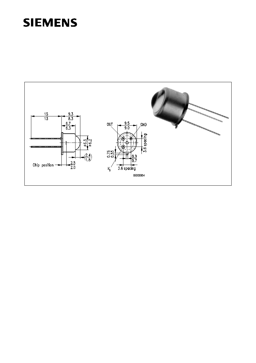
Ultraviolet Selective Sensor
SFH 530
Ma▀e in mm, wenn nicht anders angegeben/Dimensions in mm, unless otherwise specified.
Wesentliche Merkmale
Ę Hohe UV-Empfindlichkeit
Ę Speziell geeignet f³r Anwendungen bei
310 nm
Ę Geringe Empfindlichkeit bei sichtbarem und
IR-Licht
Ę Eine Versorgungsspannung
Ę Geringe Stromaufnahme
Ę Hermetisch dichte Metallbauform (TO-39)
Anwendungen
Ę Flammenmelder
Ę Chem. und biomedizinische Analyse
Ę Photometrie
Ę Excimerlasersteuerung und -³berwachung
Ę Umwelt-Kartierung
Ę Hautbestrahlungsforschung
Ę ▄berwachung von UV-Sterilisierungs-
gerõten
Ę Medizinische Fehlerdiagnose
Ę Schwei▀proze▀³berwachung
Features
Ę High UV sensitivity
Ę Suitable esp. for applications at 310 nm
Ę Low sensitivity for visible and infrared light
Ę Single supply voltage
Ę Low current consumption
Ę Hermetically sealed metal package (TO-39)
Applications
Ę Flame detector
Ę Chemical and biomedical analysis
Ę Photometry
Ę Excimer laser control and monitoring
Ę Environment mapping
Ę Skin irradiation studies
Ę Monitoring of UV sterilising equipment
Ę Medical diagnostic
Ę Welding monitoring

SFH 530
Semiconductor Group
2
1998-08-27
Grenzwerte
Maximum Ratings
Typ
Type
Bestellnummer
Ordering Code
SFH 530
Q62702-P1706
Bezeichnung
Description
Symbol
Symbol
Wert
Value
Einheit
Unit
Betriebs- und Lagertemperatur
Operating and storage temperature range
T
op
;
T
stg
Ł 20 ... + 80
░
C
Versorgungsspannung
Supply voltage
V
S
8
V
Kennwerte
(T
A
= 25
░
C)
Characteristics
Bezeichnung
Description
Symbol
Symbol
Wert
Value
Einheit
Unit
min.
typ.
max.
Versorgungsstrom
Supply current
5 V, 20
░
C, dark, no load
I
S
50
65
90
Ą
A
Max. Ausgangsstrom
Max. output current
5 V, 20
░
C, saturation, 1.4 k
load
I
out
35
51
72
Ą
A
Schwingungsbreite f³r die Ausgangsspannung
Output swing
5 V, 20
░
C, saturation, no load
5 V, 20
░
C, dark, no load
Ł
2.1
0
2.6
0.2
3.1
1
V
mV
PSRR (50 ... 100 Hz)
5 V, 20
░
C, no load
Ł
40
Ł
62
dB
Offsetspannung
Offset voltage
5 V, 25
░
C, no load
5 V, 60
░
C, no load
5 V, 80
░
C, no load
V
off
Ł 5
Ł 10
Ł 60
0
Ł 2
Ł 10
1
0
Ł 1
mV
Halbwinkel
Half angle
Ł
▒
7.5
Ł
Grad
Deg.
NEP at 310 nm
5 V, 20
░
C, no load
NEP
Ł
7
ū
10
-14
Ł
W
/
Hz
SFH 530
Semiconductor Group
3
1998-08-27
(1)
Aufgrund der Lichtb³ndelung der Linse.
Due to the light concentration of the lens.
(2)
Selektivitõt =
max
{
Empfindlichkeit von 400 nm bis 1200 nm
}
_________________________________________________
Empfindlichkeit bei 310 nm
Selectivity =
max
{
Responsivity in the range of 400 ... 1200 nm
}
___________________________________________________
Responsivity at 310 nm
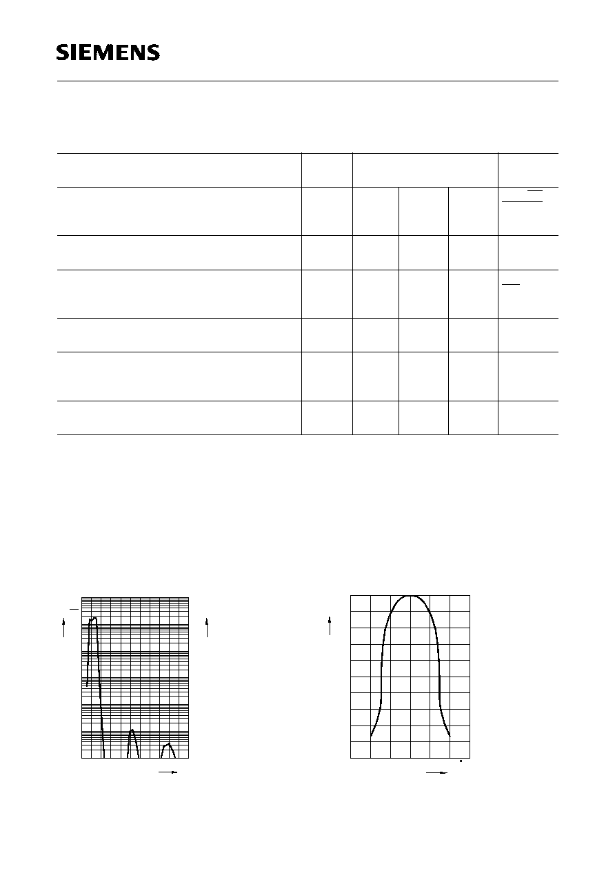
Fig. 1
Typ. spektr. Verhalten des UV Sensors
Typ. spectr. response of the UV sensor
Nachweisgrenze,
= 310 nm
Detection limit
5 V, 20
░
C, no load
D
*
Ł
5
ū
10
11
Ł
m Ę
Hz
W
Aktive Flõche
Active area (1)
A
10
11
12
mm
2
Empfindlichkeit bei 310 nm
Responsivity at 310 nm
5 V, 20
░
C, no load
Ł
135
Ł
Ł
mV
nW/mm
2
Selectivity (2)
5 V, 20
░
C, no load
Ł
Ł
Ł
10
-4
Ł
Responsivity to a 2856 K quartz-halogen lamp
without UV (glass filter GG400)
5 V, 20
░
C, no load
Ł
Ł
Ł
0.5
mV/lx
Transimpedanz
Transimpedance
Ł
1.1
1.3
1.5
G
Kennwerte
(T
A
= 25
░
C)
Characteristics (cont'd)
Bezeichnung
Description
Symbol
Symbol
Wert
Value
Einheit
Unit
Wavelength
OHF00262
200
10
-4
10
2
-3
10
-2
10
1
10
0
10
10
-1
Responsivity
-1
10
10
0
10
1
10
-2
10
-3
2
10
-4
10
Quantum Efficiency
400
600
800
1000
nm 1300
mV
%
nW
OHF00425
0
out rel
V
-15
-10
-5
0
5
10
15
0.1
0.2
0.3
0.4
0.5
0.6
0.7
0.8
0.9
1.0
)
(
Fig. 2
Empfangscharakteristik
Response characteristic
V
out
=
f
(
)

SFH 530
Semiconductor Group
4
1998-08-27
Ultraviolet Selective Sensor
Allgemeines
Der SFH 530, ein ultraviolett (UV)-selektiver op-
tischer Sensor, wurde speziell f³r die hohen An-
forderungen an die Flammen³berwachung in
ųlbrennern (Blaubrenner) entwickelt und ist f³r
viele weitere anspruchsvolle Me▀aufgaben im
Bereich der UV-Detektion einsetzbar. Die Foto-
diode und die Verstõrkerschaltung (Verstõr-
kung des Fotostromes, Umsetzung in ein Span-
nungssignal) befinden sich in einem hermetisch
dichten TO-39 Gehõuse mit drei Anschlu▀pins
(GND,
V
s
: Betriebsspannung, OUT: Ausgangs-
spannung). Das Gehõuse bietet besonderen
Schutz vor St÷rungen durch elektromagneti-
sche Felder und vor Feuchtigkeit ³ber den ge-
samten Betriebstemperaturbereich von Ł 20 ░C
bis + 80 ░C.
Optisches Verhalten
Das optische Verhalten des SFH 530 wird
durch die Kombination aus einer UV-durchlõssi-
gen Sammellinse, einem UV-Filterglas und ei-
ner Si-Fotodiode mit hoher Selektivitõt f³r
UV-Strahlung bestimmt. Die Selektivitõt im Wel-
lenlõngenbereich von 290 nm bis 350 nm wird
durch eine definierte Dotierung der Fotodiode
und ein aufgedampftes Interferenzfilter erreicht.
Dadurch wird der Einflu▀ sichtbarer und infraro-
ter Strahlung auf das Nutzsignal stark unter-
dr³ckt. Die Empfindlichkeit f³r Wellenlõngen
400 nm ist stets kleiner als ein Zehntausend-
stel der maximalen Empfindlichkeit bei
ca. 310 nm.
Ultraviolet Selective Sensor
General
The SFH 530, an ultraviolet (UV) selective opti-
cal sensor has been specially developed for the
exacting requirements placed on flame monitor-
ing in oil burners and can be used for many oth-
er important measuring tasks in the UV detec-
tion area. The photodiode and the amplifier cir-
cuit (amplification of the photocurrent, conver-
sion to a voltage signal) are housed in a hermet-
ically sealed TO-39 package with three terminal
pins (GND,
V
s
: operating voltage, OUT: output
voltage). The package is specially protected
against electromagnetic interference and mois-
ture over the entire operating temperature
range of Ł 20 ░C to + 80 ░C.
Optical Characteristics
The optical behavior of the SFH 530 is deter-
mined by the combination of a UV-permeable
focusing lens, a UV filter glass and a Si photo-
diode with high selectivity for UV radiation. The
selectivity in the wavelength range 290 to
350 nm is achieved by means of a defined dop-
ing of the photodiode and a vapor-deposited in-
terference filter. This heavily suppresses the ef-
fect of visible and infrared radiation on the sig-
nal. The sensitivity to wavelengths
400 nm is
always less than one ten-thousandth of the
maximum sensitivity at approximately 310 nm.

SFH 530
Semiconductor Group
5
1998-08-27
Elektrisches Verhalten
Ę Betrieb mit nur einer Versorgungsspannung
Ę Der Fotostrom der UV-Diode liegt typischer-
weise bei
I
ph
= 100 pA. F³r ein hohes Aus-
gangssignal mu▀ der R³ckkopplungswider-
stand
R
1
der Verstõrkerschaltung sehr hoch-
ohmig typ.1 G
sein.
Die wesentlichen elektrischen Funktionen des
UV-Sensors zeigt das Ersatzschaltbild (Bild 3).
Bild 3
Ę
V
out
= (
I
ph
-
I
L
)
R
k
+
V
off
(1 +
R
1
/
R
d
)
Ę F³r oszillierende Beleuchtungsstõrken stellt
die Schaltung einen Tiefpa▀ erster Ordnung
mit einer Grenzfrequenz von typisch 100 Hz
dar.
Temperaturverhalten:
I
L
: ist bei Raumtemperatur typisch < 1 pA
und verdoppelt sich alle 12 ░C
R
d
: ist bei Raumtemperatur typisch > 10 G
,
besteht aus der Parallelschaltung der ent-
sprechenden Widerstõnde des
Ł Rekombinationsstromes
(verdoppelt sich alle 12 ░C),
Ł Diffusionsstromes
(verdoppelt sich alle 5.6 ░C)
Electrical Characteristics
Ę Operated from a single supply voltage.
Ę The photocurrent of the UV diode is typically
I
ph
= 100 pA. For a high output signal the val-
ue of the feedback resistor
R
1
in the amplifier
circuit must be very high typ. 1 G
.
The main electrical functions of the UV sensor
are shown in the equivalent circuit diagram
(Figure 3).
Figure 3
Ę
V
out
= (
I
ph
-
I
L
)
R
k
+
V
off
(1 +
R
1
/
R
d
)
Ę For oscillating illuminances the circuit consti-
tutes a first-order lowpass filter with a cutoff
frequency of typically 100 Hz.
Temperature behavior:
I
L
: is typically < 1 pA at room temperature
and doubles every 12 ░C
R
d
: is typically > 10 G
(at room temperature,
consisting of the parallel connection of the
corresponding resistances of the
Ł recombination current
(doubles every 12 ░C),
Ł diffusion current
(doubles every 5.6 ░C)

SFH 530
Semiconductor Group
6
1998-08-27
Ę Das Temperaturverhalten zeigt gro▀en Ein-
flu▀ auf das Ausgangssignal des Sensors.
Der ASIC ist so ausgelegt, da▀ er bei Raum-
temperatur 0 ... Ł 1 mV Offset und einen ne-
gativen Temperaturkoeffizienten aufweist.
Auch auftretende Leckstr÷me w³rden das
Nutzsignal nur verringern (der Leckstrom ist
stets subtraktiv bez³glich des Ausgangssig-
nals).
Ę The temperature behavior shows the marked
effect on the sensor's output signal. The
ASIC is so designed that it exhibits a 0 to
Ł 1 mV offset and a negative temperature
coefficient at room temperature. Even any
leakage currents present would only reduce
the wanted signal (the leakage current is al-
ways subtractive with respect to the output
signal).