
ELECTRONIC COMPONENTS
SHARP IrDA Control Infrared Transceiver
SHARP Electronic Components
1
Rev. 1.0.1, November 26, `98
GP2W2002YK
IrDA Control Infrared Transceiver
for Peripheral Type 2
Revision 1.0.1
November 26, 1998
SHARP CORPORATION

ELECTRONIC COMPONENTS
SHARP IrDA Control Infrared Transceiver
SHARP Electronic Components
2
Rev. 1.0.1, November 26, `98
Record of Modification and Revision
Version
Issue Date
Comments
0.9
August 18th, 1998
First Edition
0.91
August 25th, 1998
Outline Dimension and Absolute Maximum Ratings Modified
1.0
October 23rd,1998
Absolute Ratings and Electrical Characteristics Modified
1.0.1
November 26th,1998
Electrical and Optical Specifications Modified
(Preliminary Information Disclaimer)
This document includes a "Preliminary Information" of Sharp IrDA Control Infrared Transceiver (for IrDA Control
Peripheral Type 2). Any of information under this document, such as Specifications and outline dimensions, are
applicable only for reference purpose, and Sharp hold all rights to change or alter prices at any time without notice.
In absence of confirmation by device Specification Sheets, SHARP takes no responsibility for any defects that occur in
equipment using any of SHARP's device, shown in catalogues, data books, Preliminary Information, etc. Contact
SHARP, or SHARP local representatives in order to obtain the latest version of the device Specification Sheets before
using any SHARP's devices.

ELECTRONIC COMPONENTS
SHARP IrDA Control Infrared Transceiver
SHARP Electronic Components
3
Rev. 1.0.1, November 26, `98
Table Of Contents
1. DESCRIPTION .............................................................................................................................................................. 4
2. IRDA CONTROL INFRARED TRANSCEIVER INTERNAL BLOCK DIAGRAM .................................................. 4
3. PACKAGE OUTLINE DIMENSIONS (TENTATIVE)................................................................................................ 5
4. ABSOLUTE MAXIMUM RATINGS............................................................................................................................ 5
5. RECOMMENDED OPERATING CONDITIONS ........................................................................................................ 6
6. ELECTRICAL AND OPTICAL SPECIFICATIONS.................................................................................................... 7
7. PINOUT ......................................................................................................................................................................... 8
8. APPLICATION CIRCUIT AND RECOMMENDED COMPONENTS........................................................................ 9
9. WAVEFORM EXAMPLES........................................................................................................................................... 9
10. RESET FUNCTION................................................................................................................................................... 10
11. THE DERATING CURVE OF PEAK FORWARD LED CURRENT ...................................................................... 10
ELECTRONIC COMPONENTS
SHARP IrDA Control Infrared Transceiver
SHARP Electronic Components
4
Rev. 1.0.1, November 26, `98
IrDA Control Infrared Transceiver (for Peripheral Type 2)
GP2W2002YK
Technical Data
MEMBER IrDA
1. Description
The Sharp IrDA Control Infrared Transceiver provides
the wireless interface between logic and IR signals for
through-air, serial, half-duplex IrDA Control data links
and is designed to satisfy the IrDA Control Physical
Layer Specifications for Peripheral Type 2.
The GP2W2002YK is a low power operatable integrated
infrared transceiver that contains an IRLED, a LED
driver circuit, a PIN photodiode, an excellent sensitivity
receiver, and an envelope detector. The transceiver also
contains some additional functions, such as shut down
and sensitivity recovery for low current consumption and
longer communication distance.
<Features>
�
Meets IrDA Control (for Peripheral Type 2)
�
Wide Viewing Angle ([Min.] 1.5 m @ +/-40
o
)
Wireless Communication at 75kbps data rate
�
Low Power Operation - at 3.3V
�
Built-in Envelope Detector
�
RESET Function to Recover the Receiver
Sensitivity
�
Optimized Interface to Sharp Peripheral Engine, an
embedded communication controller for IrDA
Control.
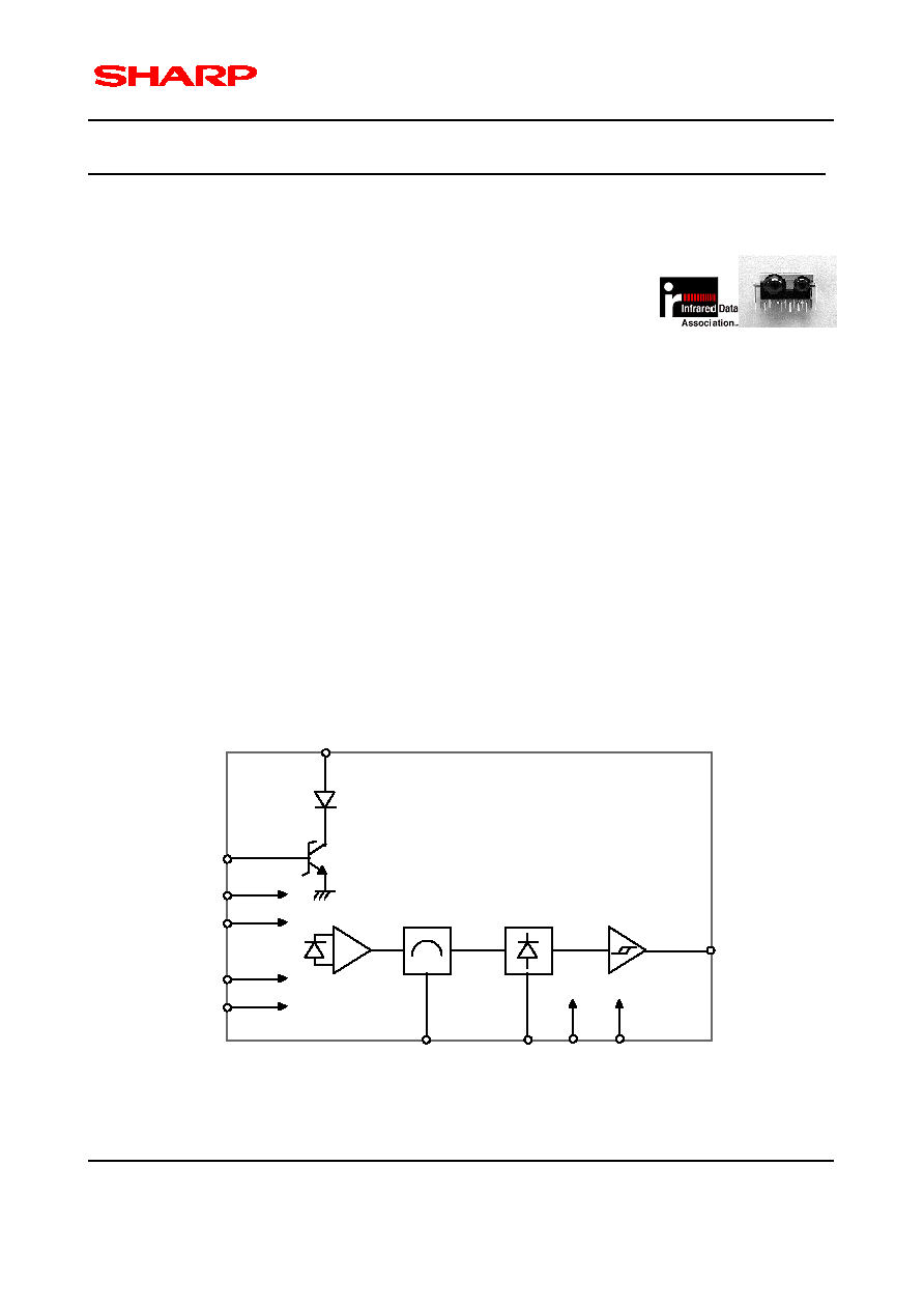
2. IrDA Control Infrared Transceiver Internal Block Diagram
LEDA
TXD
AVcc
DVcc
AGND
DGND
f
O
CX
RESET
V
O
10
1
6
5
7
9
4
3
8
PIN
PD
AMP.
B.P.F.
Detect
11
SD
2
Figure 2.1 GP2W2002YK Internal Block Diagram

ELECTRONIC COMPONENTS
SHARP IrDA Control Infrared Transceiver
SHARP Electronic Components
5
Rev. 1.0.1, November 26, `98
3. Package Outline Dimensions (TENTATIVE)
UNIT: mm
17.5
14.0
1.27
0.25
(0.89)
(8.2)
(3.7)
4.5
3.1
0.45
(0.84)
(2.08)
2.5
SHIELD CASE
(5.35)
0.9
3.35
1.2
2.0
1.3
(7.6)
1.
Unspecified tolerance shall be � 0.3(mm).
2.
Resin burr shall not be included in outline dimensions.
3.
Package Material : Visible Light Cut-off Resin (Color: Black)
4.
Pin Assignment : See "Pinout" for details.
5.
Lead pitch distance represents that of the lead root.
6.
The appearance of the shieled case is TENTATIVE, and is subject to change without notice.
4. Absolute Maximum Ratings
Parameter
Symbol
Min.
Max.
Units
Conditions
Supply Voltage
V
CC
0
6.0
V
Operating Temperature
T
OP
-10
70
o
C
Storage Temperature
T
ST
-20
85
o
C
Average Forward LED Current
I
FD
(DC)
-
60
mA
Peak Forward LED Current
I
FM
-
600
mA
*1
Transmitter Data Input Current
I
TXD
-
5.0
mA
Receiver Data Output Voltage
V
O
-
V
CC
V
Soldering Temperature
T
SOL
-
260
o
C
*2
, For 5s
(NOTES)
1.
The derating curve of peak forward current vs. ambient temperature is shown in section 11, figure 11.1.
2.
The soldering should be done at the distance from 1.3mm from the resin edge of the transceiver module.