1.
General description
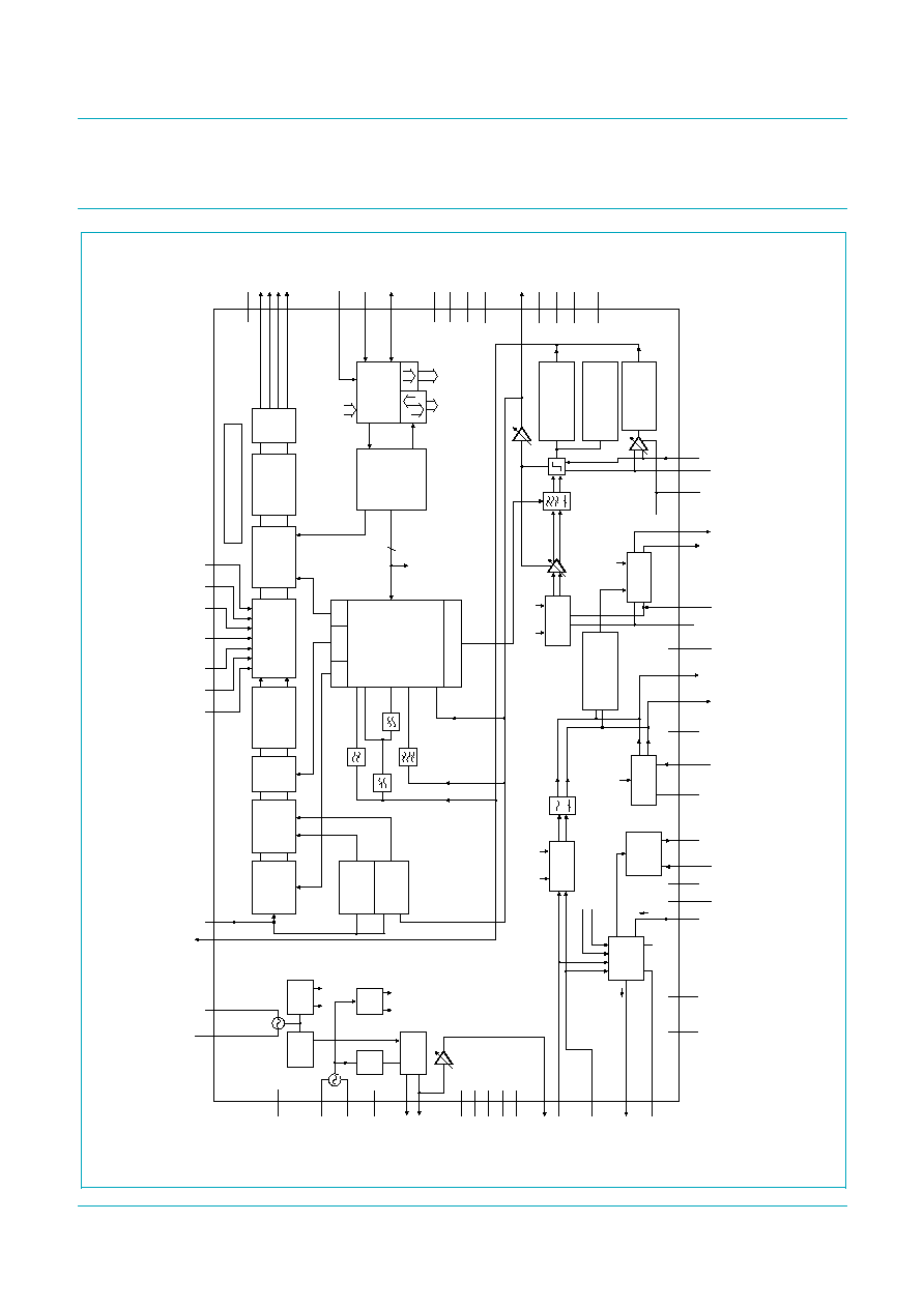
The TEF6902A is a single-chip car radio integrated circuit with FM/AM tuner, stereo
decoder, weak signal processing and audio processing.
FM tuner with double conversion to IF1 = 10.7 MHz and IF2 = 450 kHz with integrated
image rejection for both IF1 and IF2; integrated channel filter with variable bandwidth
control; capable of US FM, Europe FM, Japan FM and Eastern Europe FM. AM tuner with
double conversion to IF1 = 10.7 MHz and IF2 = 450 kHz; capable of Long Wave (LW),
Medium Wave (MW) and full range Short Wave (SW) (11 m to 120 m bands).
Multiplex (MPX) stereo decoder, ignition noise blanker and extensive weak signal
processing.
Audio processing with flexible source selection, volume, balance, fader, input gain control
and inaudible tuning mute. Integrated audio filters for bass and treble and loudness control
function.
The device can be controlled via the fast-mode I
2
C-bus (400 kHz) and includes
autonomous tuning functions for easy control without microcontroller timing. No manual
alignments are required.
2.
Features
I
FM Radio Frequency (RF) front-end with large dynamic range
I
Integrated FM channel filter with controlled bandwidth
I
Fully integrated FM demodulator
I
Fully integrated stereo decoder with high immunity for birdy noise
I
FM noise blanker with adaptive detection at MPX and level
I
Signal quality detection: level, AM wideband, frequency deviation, ultrasonic
noise/adjacent channel
I
FM weak signal processing: stereo blend, high cut control and soft mute
I
AM RF Automatic Gain Control (AGC) circuit for external cascode AGC and PIN diode
AGC
I
Dual AM noise blanking system
I
AM weak signal processing: high cut control and soft mute
I
Low phase noise local oscillator
I
In-lock detection for optimized adaptive Phase-Locked Loop (PLL) tuning speed
I
Crystal oscillator reference with low harmonics
I
Inaudible soft slope tuning mute for AM and FM
I
Sequential state machine supporting each tuning action
I
Flexible audio input source selection
TEF6902A
Integrated car radio
Rev. 02 -- 11 July 2006
Product data sheet

TEF6902A_2
© Koninklijke Philips Electronics N.V. 2006. All rights reserved.
Product data sheet
Rev. 02 -- 11 July 2006
2 of 106
Philips Semiconductors
TEF6902A
Integrated car radio
I
Integrated audio processing and tone filtering
I
Treble, bass and loudness tone control
I
Volume, balance, fader and input gain control
I
Audio controls with Audio Step Interpolation (ASI) for pop-free function
I
Compact Disc (CD) dynamics compression
I
Volume Unit (VU)-meter audio level read-out
3.
Quick reference data
Table 1:
Quick reference data
Symbol
Parameter
Conditions
Min
Typ
Max
Unit
Supply voltage
V
CC
analog supply voltage on pins VCC,
VCCPLL, VCCVCO, VCCRF,
AMMIX2OUT1, AMMIX2OUT2,
MIX1OUT1 and MIX1OUT2
8
8.5
9
V
Supply current in FM mode
I
CC
total supply current inclusive I
V60
-
102
-
mA
Supply current in AM mode
I
CC
total supply current inclusive I
V60
-
89
-
mA
AM overall system parameters
f
tune
AM tuning frequency
LW
144
-
288
kHz
MW
522
-
1710
kHz
SW
2.3
-
26.1
MHz
V
sens
sensitivity voltage
f
RF
= 990 kHz; m = 0.3;
f
mod
= 1 kHz; B
AF
= 2.15 kHz;
(S+N)/N = 26 dB; dummy aerial
15 pF/60 pF
-
50
-
µ
V
S/N
ultimate signal-to-noise ratio
54
58
-
dB
THD
total harmonic distortion
200
µ
V < V
RF
< 1 V; m = 0.8;
f
AF
= 400 Hz
-
0.4
1
%
IP3
3rd-order intercept point
f = 40 kHz
-
130
-
dB
µ
V
FM overall system parameters
f
tune
FM tuning frequency
65
-
108
MHz
V
sens
sensitivity voltage (RF input voltage
at (S+N)/N = 26 dB)
f = 22.5 kHz; f
mod
= 1 kHz;
DEMP = 1; B = 300 Hz to 22 kHz;
measured with 75
dummy
antenna and test circuit
-
2
-
µ
V
(S+N)/N
maximum signal plus noise-to-noise
ratio of MPXAM output voltage
V
i
= 3 mV;
f = 22.5 kHz;
f
mod
= 1 kHz; DEMP = 1;
B = 300 Hz to 22 kHz; measured
with 75
dummy antenna and test
circuit
-
60
-
dB
THD
total harmonic distortion
f = 75 kHz
-
0.5
1
%
IP3
3rd-order intercept point
f = 400 kHz
-
120
-
dB
µ
V

TEF6902A_2
© Koninklijke Philips Electronics N.V. 2006. All rights reserved.
Product data sheet
Rev. 02 -- 11 July 2006
3 of 106
Philips Semiconductors
TEF6902A
Integrated car radio
[1]
The input gain setting ING and the volume setting VOL define the overall volume. The overall range is limited to
-
83 dB to +28 dB. For
values > +28 dB the actual value is +28 dB. For overall values <
-
83 dB the actual value is mute.
4.
Ordering information
Stereo decoder path
cs
channel separation
f
FMMPX
= 1 kHz
40
-
-
dB
S/N
signal-to-noise ratio
f
MPXAMIN
= 20 Hz to 15 kHz;
referenced to 1 kHz at 91 % FM
modulation; DEMP = 1
70
-
-
dB
THD
total harmonic distortion
FM mode; DEMP = 1; measured
with 15 kHz brick-wall low-pass
filter; f
MPXAMIN
= 200 Hz to 15 kHz
-
-
0.3
%
Tone/volume control
V
i(max)
maximum input voltage
THD = 0.2 %; G
vol
=
-
6 dB;
pins INAL, INAR, INAC, INBL,
INBR, INC and IND
2
-
-
V
THD
total harmonic distortion
configured as non-inverting,
single-ended inputs;
f
audio
= 20 Hz to 10 kHz;
V
i
= 1 V (RMS)
-
0.02
0.1
%
G
vol
volume/balance gain control
see
Table 83
maximum setting
[1]
-
20
-
dB
minimum setting
[1]
-
-
75
-
dB
G
step(vol)
step resolution
-
1
-
dB
G
treble
treble gain control
TRE[2:0] = 111; TREM = 1
-
14
-
dB
TRE[2:0] = 111; TREM = 0
-
-
14
-
dB
G
step(treble)
step resolution gain
-
2
-
dB
G
bass
bass gain control
BAS[3:0] = 0111; BASM = 1
-
14
-
dB
BAS[3:0] = 0111; BASM = 0
-
-
14
-
dB
G
step(bass)
step resolution gain
-
2
-
dB
Table 1:
Quick reference data
...continued
Symbol
Parameter
Conditions
Min
Typ
Max
Unit
Table 2.
Ordering information
Type number
Package
Name
Description
Version
TEF6902AH
QFP64
plastic quad flat package; 64 leads (lead length 1.6 mm); body 14
×
14
×
2.7 mm SOT393-1
TEF6902A_2
© Koninklijke Philips Electronics N.V. 2006. All rights reserved.
Product data sheet
Rev. 02 -- 11 July 2006
5 of 106
Philips Semiconductors
TEF6902A
Integrated car radio
6.
Pinning information
6.1 Pinning
6.2 Pin description
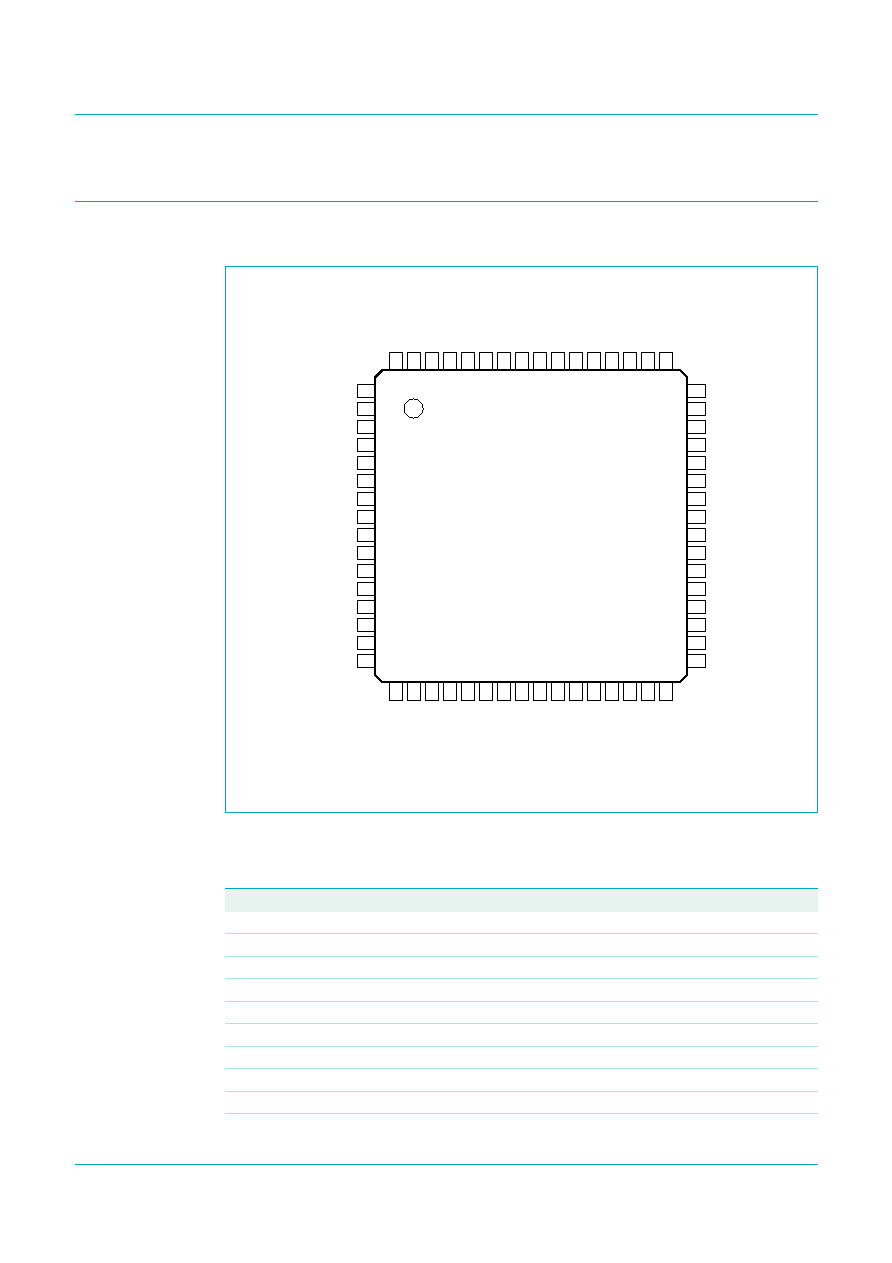
Fig 2.
Pin configuration for QFP64
TEF6902AH
CPOUT
LFOUT
VTUNE
RFOUT
VCCPLL
LROUT
PLLGND
RROUT
i.c.
ADDR
VTCM
SCL
VTC
SDA
IFMAGC
DGND2
TRFAGC
i.c.
DAAOUT
i.c.
FMMIX1IN1
DGND1
FMMIX1IN2
LEVEL
VCCRF
VCC
RFGND
GND
IAMAGC
VREF
i.c.
V60
VDCPIN
VCOGND
VAMCASFB
VCOTNK
VAMCAS
VCOFDB
AMMIX1DEC
VCCVCO
AMMIX1IN
MPXAMOUT
AMMIX1REF
MPXAMIN
MIX1OUT1
INAL
MIX1OUT2
INAR
IFGND
INAC
IF1DEC
INBL
IF1IN
INBR
AMMIX2OUT1
INC
AMMIX2OUT2
IND
TAMIFKAGC
XTAL2
AMIF2DEC
XTAL1
AMIF2IN
AGND
008aaa011
1
2
3
4
5
6
7
8
9
10
11
12
13
14
15
16
48
47
46
45
44
43
42
41
40
39
38
37
36
35
34
33
17
18
19
20
21
22
23
24
25
26
27
28
29
30
31
32
64
63
62
61
60
59
58
57
56
55
54
53
52
51
50
49
Table 3.
Pin description
Symbol
Pin
Description
CPOUT
1
charge pump output
VTUNE
2
tuning voltage; 3 mA charge pump output
VCCPLL
3
tuning PLL supply voltage
PLLGND
4
PLL ground
i.c.
5
internally connected; leave open
VTCM
6
Intermediate Frequency (IF) filter reference voltage
VTC
7
IF filter center voltage
IFMAGC
8
PIN diode current FM AGC
TRFAGC
9
FM and AM RF AGC time constant
DAAOUT
10
antenna Digital Auto Alignment (DAA) output