
DATA SHEET
Product specification
File under Integrated Circuits, IC01
March 1994
INTEGRATED CIRCUITS
TEA5710; TEA5710T
AM/FM radio receiver circuit

March 1994
2
Philips Semiconductors
Product specification
AM/FM radio receiver circuit
TEA5710; TEA5710T
FEATURES
À
Wide supply voltage range: 2.0 to 12 V
À
Low current consumption: 7.5 mA at AM, 9.0 mA at FM
À
High selectivity with distributed IF gain
À
LED driver for tuning indication
À
High input sensitivity: 1.6 mV/m (AM), 2.0
Á
V (FM) for 26
dB S/N
À
Good strong signal behaviour: 10 V/m at AM, 500 mV at
FM
À
Low output distortion: 0.8% at AM, 0.3% at FM
À
Designed for simple and reliable PC-board layout
À
High impedance MOSFET input on AM
APPLICATIONS
À
Portable AM/FM radio
À
Clock radio
À
Personal headphone radio
DESCRIPTION
The TEA5710 is a high performance Bimos IC for use in
AM/FM radios. All necessary functions are integrated:
from AM and FM front-end to detector output stages.
QUICK REFERENCE DATA
Conditions AM: f
i
= 1 MHz; m = 0.3; f
m
= 1 kHz; V
P
= 3.0 V; measured in Fig.4 with S1 in position B and S2 in position A,
unless otherwise specified. Conditions FM: f
i
= 100 MHz;
f = 22.5 kHz; f
m
= 1 kHz; V
P
= 3.0 V; measured in Fig.4 with
S1 in position B and S2 in position A, unless otherwise specified.
ORDERING INFORMATION
Notes
1. SOT234-1; 1996 August 27.
2. SOT137-1; 1996 August 27.
SYMBOL
PARAMETER
MIN.
TYP.
MAX.
UNIT
V
P
positive supply voltage
2.0
-
12
V
I
P
supply current
in AM mode
5.6
7.5
9.9
mA
in FM mode
7.3
9.0
11.2
mA
T
amb
operating ambient temperature range
-
15
-
+
60
░
C
AM performance
V
in1
RF sensitivity
40
55
70
Á
V
V
13
AF output voltage
36
45
70
mV
THD
total harmonic distortion
-
0.8
2.0
%
FM performance
V
in3
RF sensitivity
1.0
2.0
3.8
Á
V
V
13
AF output voltage
47
58
69
mV
THD
total harmonic distortion
-
0.3
0.8
%
EXTENDED TYPE
NUMBER
PACKAGE
PINS
PIN POSITION
MATERIAL
CODE
TEA5710
24
SDIL
plastic
SOT234AG
(1)
TEA5710T
24
SO24L
plastic
SOT137A
(2)
March 1994
3
Philips Semiconductors
Product specification
AM/FM radio receiver circuit
TEA5710; TEA5710T
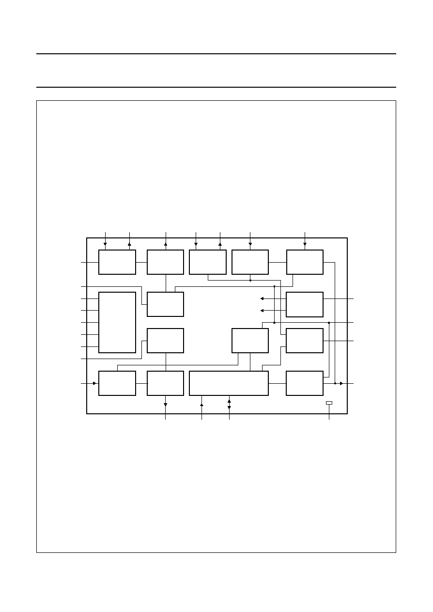
Fig.1 Block diagram.
handbook, full pagewidth
MGE106
FM-RFI FM-RFO
FM-MIXER
FM
FRONT-END
FM
MIXER
AM
FRONT-END
FM-IF1I
FM-RF1O
FM
IF 1
FM-IF2I
FM
IF 2
FM-DEM
FM
DETECTOR
AM
MIXER
FM
OSCILLATOR
AM
OSCILLATOR
AM/FM
INDICATOR
AM/FM
SWITCH
AM
DETECTOR
STABILIZER
24
1
20
4
6
8
10
12
18
16
22
5
9
11
17
23
3
2
7
19
13
15
21
14
AM-IF
AGC
FM
AM
RFGND
AM/FM
IND
AF
AM-AGC/
FM-AFC
FM-OSC
VP
RIPPLE
VSTABA
VSTABB
IFGND
AM-OSC
AM-RFI
AM-IF1I AM-IF2I/O
AM-MIXER
SUBGND
TEA5710
TEA5710T

March 1994
4
Philips Semiconductors
Product specification
AM/FM radio receiver circuit
TEA5710; TEA5710T
PINNING
SYMBOL
PIN
DESCRIPTION
FM-RF
I
1
FM-RF aerial input (input impedance typ. 50
)
AM-IF1
I
2
input from IFT or ceramic filter (input impedance typ. 3 k
)
AM-MIXER
3
open-collector output to IFT
FM-MIXER
4
output to ceramic IF filter (output impedance typ. 330
)
VSTAB
A
5
stabilized internal supply voltage (A)
FM-IF1
I
6
first FM-IF input (input impedance typ. 330
)
AM-IF2
I/O
7
input/output to IFT; output: current source
FM-IF1
O
8
first FM-IF output (output impedance typ. 330
)
VSTAB
B
9
stabilized internal supply voltage (B)
FM-IF2
I
10
second FM-IF input (input impedance typ. 330
)
IFGND
11
ground of IF and detector stages
FM-DEM
12
ceramic discriminator pin
AF
13
audio output (output impedance typ. 5 k
)
AM/FM
14
switch terminal: open for AM; ground for FM
IND
15
field-strength dependent indicator
V
P
16
positive supply voltage
AM-OSC
17
parallel tuned AM-OSC circuit to ground
FM-OSC
18
parallel tuned FM-OSC circuit to ground
SUBGND
19
substrate and RF ground
FM-RF
O
20
parallel tuned FM-RF circuit to ground
AM-AGC/FM-AFC
21
AGC/AFC capacitor pin
RIPPLE
22
ripple capacitor pin
AM-RF
I
23
parallel tuned AM aerial circuit to ground (total input capacitance typ. 3 pF)
RFGND
24
FM-RF ground
March 1994
5
Philips Semiconductors
Product specification
AM/FM radio receiver circuit
TEA5710; TEA5710T
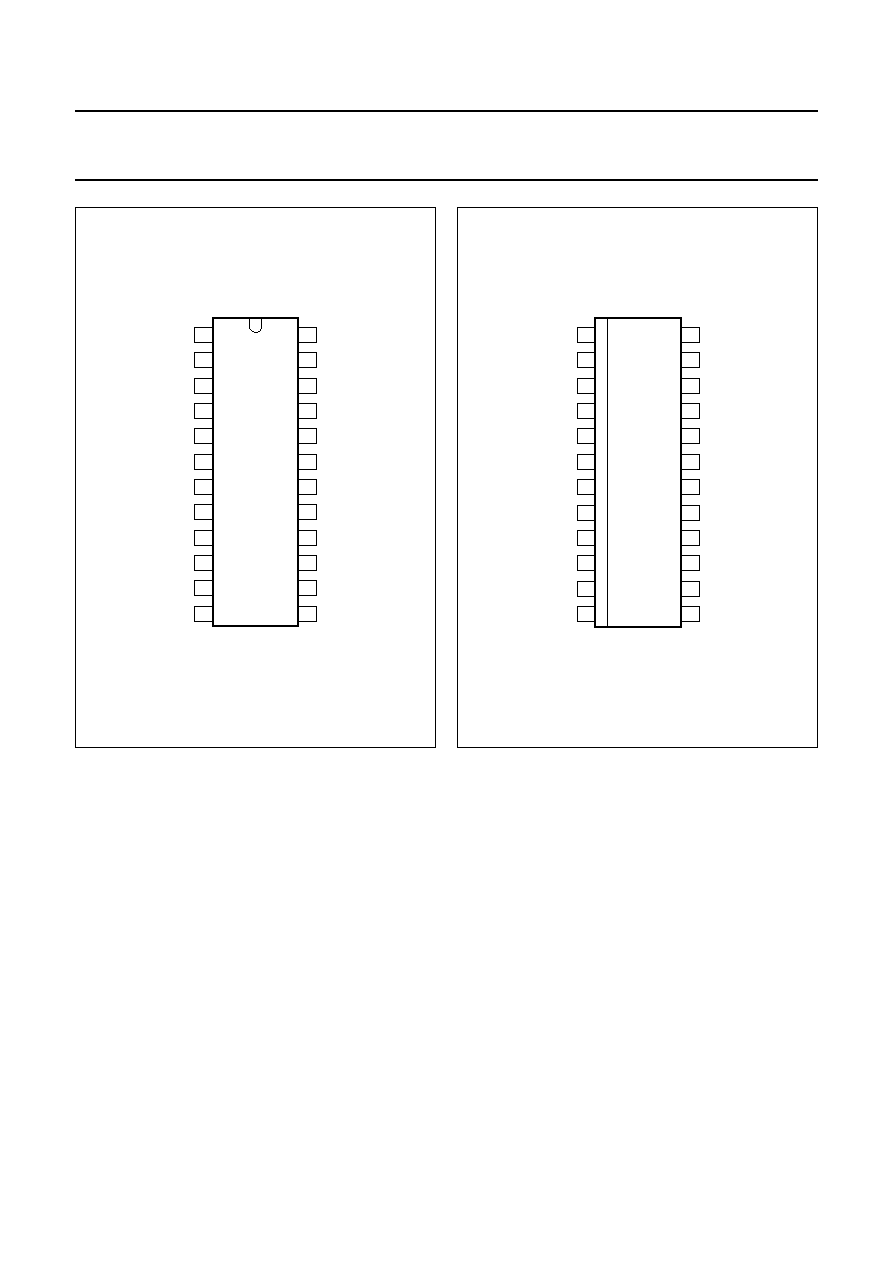
Fig.2 Pin configuration TEA5710.
handbook, halfpage
TDA5710
MGE104
1
2
3
4
5
6
7
8
9
10
11
12
24
23
22
21
20
19
18
17
16
15
14
13
FM-RFI
AM-IFI
AM-MIXER
FM-MIXER
VSTABA
FM-IF1I
AM-IF2I/O
FM-IF1O
VSTABB
FM-IF2I
IFGND
FM-DEM
RFGND
AM-RFI
RIPPLE
AM-AGC/FM-AFC
SUBGND
FM-OSC
FM-RFO
AM-OSC
VP
IND
AM/FM
AF
Fig.3 Pin configuration TEA5710T.
handbook, halfpage
TDA5710T
MGE105
1
2
3
4
5
6
7
8
9
10
11
12
24
23
22
21
20
19
18
17
16
15
14
13
FM-RFI
AM-IFI
AM-MIXER
FM-MIXER
VSTABA
FM-IF1I
AM-IF2I/O
FM-IF1O
VSTABB
FM-IF2I
IFGND
FM-DEM
RFGND
AM-RFI
RIPPLE
AM-AGC/FM-AFC
SUBGND
FM-OSC
FM-RFO
AM-OSC
VP
IND
AM/FM
AF
FUNCTIONAL DESCRIPTION
The TEA5710 incorporates internal stabilized power supplies. The maximum supply voltage is 12 V, the minimum voltage
can go down temporarily to 1.8 V without any loss in performance.
The AM circuit incorporates a double balanced mixer, a one pin low-voltage oscillator (up to 30 MHz), a field-strength
dependent indicator output and is designed for distributed selectivity.
The AM input is designed to be connected to the top of a tuned circuit. AGC controls the IF amplification and for large
signals it lowers the input impedance.
The first AM selectivity can be an IFT as well as an IFT combined with a ceramic filter; the second one is an IFT.
The FM circuit incorporates a tuned RF stage, a double balanced mixer, a one-pin oscillator, a field-strength indicator
output and is designed for distributed IF ceramic filters. The FM quadrature detector uses a ceramic resonator.