
1.
General description
The ISP1760 is a Hi-Speed Universal Serial Bus (USB) Host Controller with a generic
processor interface. It integrates one Enhanced Host Controller Interface (EHCI), one
Transaction Translator (TT) and three transceivers. The Host Controller portion of the
ISP1760 and the three transceivers comply to
Universal Serial Bus Specification Rev. 2.0.
The EHCI portion of the ISP1760 is adapted from
Enhanced Host Controller Interface
Specification for Universal Serial Bus Rev. 1.0.
The integrated high-performance Hi-Speed USB transceivers enable the ISP1760 to
handle all Hi-Speed USB transfer speed modes: high-speed (480 Mbit/s), full-speed
(12 Mbit/s) and low-speed (1.5 Mbit/s). The three downstream ports allow simultaneous
connection of three devices at different speeds (high-speed, full-speed and low-speed).
The generic processor interface allows the ISP1760 to be connected to various
processors as a memory-mapped resource. The ISP1760 is a slave host: it does not
require `bus-mastering' capabilities of the host system bus. The interface is configurable,
ensuring compatibility with a variety of processors. Data transfer can be performed on
16 bits or 32 bits, using Programmed Input/Output (PIO) or Direct Memory Access (DMA)
with major control signals configurable as active LOW or active HIGH.
Integration of the TT allows connection to full-speed and low-speed devices, without the
need of integrating Open Host Controller Interface (OHCI) or Universal Host Controller
Interface (UHCI). Instead of dealing with two sets of software drivers--EHCI and OHCI or
UHCI--you need to deal with only one set--EHCI--that dramatically reduces software
complexity and IC cost.
2.
Features
s
The Host Controller portion of the ISP1760 complies with
Universal Serial Bus
Specification Rev. 2.0
s
The EHCI portion of the ISP1760 is adapted from
Enhanced Host Controller Interface
Specification for Universal Serial Bus Rev. 1.0
s
Contains three integrated Hi-Speed transceivers that support the high-speed,
full-speed and low-speed modes
s
Integrates a TT for Original USB (full-speed and low-speed) device support
s
Up to 64-kbyte internal memory (8 k x 64 bits) accessible through a generic processor
interface; operation in multitasking environments is made possible by the
implementation of virtual segmentation mechanism with bank switching on task
request
ISP1760
Hi-Speed Universal Serial Bus host controller for embedded
applications
Rev. 01 -- 8 November 2004
Product data sheet

9397 750 13257
© Koninklijke Philips Electronics N.V. 2004. All rights reserved.
Product data sheet
Rev. 01 -- 8 November 2004
2 of 105
Philips Semiconductors
ISP1760
Embedded Hi-Speed USB host controller
s
Generic processor interface (nonmultiplexed and variable latency) with a configurable
32-bit or 16-bit external data bus; the processor interface can be defined as
variable-latency or SRAM type (memory mapping)
s
Slave DMA support for reducing the load of the host system CPU during the data
transfer to or from the memory
s
Integrated phase-locked loop (PLL) with a 12 MHz crystal or an external clock input
s
Integrated multiconfiguration FIFO
s
Optimized `msec-based' or `multi-msec-based' Philips Transfer Descriptor (PTD)
interrupt
s
Tolerant I/O for low voltage CPU interface (1.65 V to 3.6 V)
s
3.3 V-to-5.0 V external power supply input
s
Integrated 5.0 V-to-1.8 V or 3.3 V-to-1.8 V voltage regulator (internal 1.8 V for
low-power core)
s
Internal power-on reset and low-voltage reset
s
Supports suspend and remote wake-up
s
Target current consumption:
x
Normal operation; one port in high-speed active: I
CC
< 100 mA
x
Suspend mode: I
susp
< 150
µ
A at the room temperature
s
Built-in configurable overcurrent circuitry (digital or analog overcurrent protection)
s
Available in LQFP128 package.
3.
Applications
The ISP1760 can be used to implement a Hi-Speed USB compliant Host Controller
connected to most of the CPUs present in the market today, having a generic processor
interface with demultiplexed address and data bus. This is because of the efficient
slave-type interface of the ISP1760.
The internal architecture of the ISP1760 is such that it can be used in a large spectrum of
applications requiring a high-performance internal Host Controller.
3.1 Examples of a multitude of possible applications
s
Set-top box: for connecting external high-performance mass storage devices
s
Mobile phone: for connecting various USB devices
s
Personal Digital Assistant (PDA): for connecting a large variety of USB devices
s
Printer: for connecting external memory card readers, allowing direct printing
s
Digital Still Camera (DSC): for printing to an external USB printer, for direct printing
s
Mass storage: for connecting external memory card readers or other mass storage
devices, for direct back-up.
The low power consumption and deep power management modes of the ISP1760
make it particularly suitable for use in portable devices.

9397 750 13257
© Koninklijke Philips Electronics N.V. 2004. All rights reserved.
Product data sheet
Rev. 01 -- 8 November 2004
3 of 105
Philips Semiconductors
ISP1760
Embedded Hi-Speed USB host controller
4.
Ordering information
Table 1:
Ordering information
Type number Package
Name
Description
Version
ISP1760BE
LQFP128
plastic low profile quad flat package; 128 leads;
body 14 x 20 x 1.4 mm
SOT425-1

9397 750 13257
© Koninklijke Philips Electronics N.V. 2004. All rights reserved.
Product data sheet
Rev. 01 -- 8 November 2004
4 of 105
Philips Semiconductors
ISP1760
Embedded Hi-Speed USB host controller
5.
Block diagram
Fig 1.
Block diagram.
RISC PROCESSOR
INTERFACE:
MEMORY
MANAGEMENT
UNIT
+
SLAVE DMA
CONTROLLER
+
INTERRUPT
CONTROL
VIRTUAL SEGMENTATION
FOR MULTITASKING SUPPORT
MEMORY
ARBITER
AND FIFO
EHCI AND
OPERATIONAL
REGISTERS
PIE
TRANSACTION
TRANSLATOR
AND RAM
PORT ROUTING OR CONTROL LOGIC + HOST AND HUB PORT STATUS
HI-SPEED
USB ATX1
DP1
DM1
PSW1_N
OC1_N
PSW3_N
OC3_N
004aaa435
PLL
30 MHz
60 MHz
XTAL1
GLOBAL CONTROL
AND POWER
MANAGEMENT
POWER-ON RESET
AND V
BAT
ON
DIGITAL
AND ANALOG
OVERCURRENT
DETECTION
RESET_N
SUSPEND/
WAKEUP_N
REF5V
A[17:1]
GENERIC PROCESSOR BUS
INTERNAL MEMORY
UP TO 64 KBYTES
5 V-TO-1.8 V
VOLTAGE
REGULATOR
16-bit
or
32-bit
PTD AND PAYLOAD MEMORY:
+
HARDWARE
CONFIGURATION
REGISTERS
V
CC(5V0)
USB FULL-SPEED AND LOW SPEED DATA PATH
USB HIGH-SPEED DATA PATH
HI-SPEED
USB ATX2
HI-SPEED
USB ATX3
DP2
DM2
DP3
DM3
37 to 39, 41 to 43,
45 to 47, 49, 51,
52, 54, 56 to 58,
60 to 62, 64 to 66,
68 to 70, 72 to 74,
76 to 78, 80
82, 84, 86, 87,
89, 91 to 93,
95 to 98,
100 to 103, 105
106
CS_N
107
RD_N
108
WR_N
114
DREQ
116
DACK
112
IRQ
10, 40, 48, 59, 67,
75, 83, 94, 104, 115
XTAL2
11
12
CLKIN
13
2
20
18
27
25
21 127
19
GND
26
GND
28 128
34 33
GND
35
1
RREF1
16
GND
15
RREF2
23
GND
22
RREF3
30
GND
29
122
119
V
BAT_ON_N
110
5 V-TO-3.3 V
VOLTAGE
REGULATOR
V
REG(3V3)
V
REG(1V8)
5, 50,
85, 118
9
6, 7
GND
4, 8, 14, 17, 24,
31, 36, 44, 53,
55, 63, 71, 79,
88, 90, 99, 109,
121, 123
DATA[15:0]/DATA[31:0]
ISP1760
PSW2_N
OC2_N
V
CC(I/O)
17
32
9397 750 13257
© Koninklijke Philips Electronics N.V. 2004. All rights reserved.
Product data sheet
Rev. 01 -- 8 November 2004
5 of 105
Philips Semiconductors
ISP1760
Embedded Hi-Speed USB host controller
6.
Pinning information
6.1 Pinning
6.2 Pin description
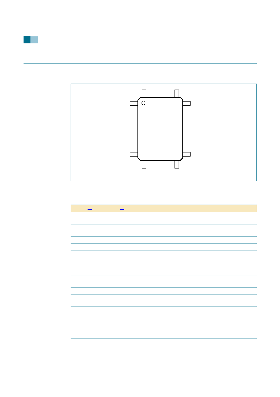
Fig 2.
Pin configuration (LQFP128).
ISP1760BE
102
39
64
12
8
10
3
65
1
38
004aaa505
Table 2:
Pin description
Symbol
[1]
Pin
Type
[2]
Description
OC3_N
1
AI
port 3 analog (5 V input) and digital overcurrent input; if not used,
connect to V
CC(I/O)
through a 10 k
resistor
REF5V
2
AI
5 V reference input for analog OC detector; connect a 100 nF
decoupling capacitor
TEST
3
-
connect to ground
GND
4
-
analog ground
V
REG(1V8)
5
P
core power output (1.8 V); internal 1.8 V for the digital core; used for
decoupling; connect a 100 nF capacitor
V
CC(5V0)
6
P
input to internal regulators (3.0 V to 5.5 V); connect a 100 nF
decoupling capacitor
V
CC(5V0)
7
P
input to internal regulators (3.0 V to 5.5 V); connect a 100 nF
decoupling capacitor
GND
8
-
oscillator ground
V
REG(3V3)
9
P
regulator output (3.3 V); for decoupling only; connect a 100 nF
capacitor and a 4.7
µ
F to 10
µ
F capacitor
V
CC(I/O)
10
P
digital supply; 1.65 V to 3.6 V; connect a 100 nF decoupling
capacitor
XTAL1
11
AI
12 MHz crystal connection input; connect to ground if an external
clock is used; see
Table 84
XTAL2
12
AO
12 MHz crystal connection output
CLKIN
13
I
12 MHz oscillator or clock input; connect to V
CC(I/O)
when not in use
3.3 V tolerant
GND
14
-
digital ground