DATA SHEET
Product specification
Supersedes data of 2003 Jul 15
2004 Mar 10
DISCRETE SEMICONDUCTORS
BC847M series
NPN general purpose transistors
M3D883
BOTTOM VIEW
2004 Mar 10
2
Philips Semiconductors
Product specification
NPN general purpose transistors
BC847M series
FEATURES
·
Leadless ultra small plastic package
(1 mm
×
0.6 mm
×
0.5 mm)
·
Board space 1.3
×
0.9 mm
·
Power dissipation comparable to SOT23.
APPLICATIONS
·
General purpose small signal DC
·
Low and medium frequency AC applications
·
Mobile communications, digital (still) cameras, PDAs,
PCMCIA cards.
DESCRIPTION
NPN general purpose transistor in a SOT883 leadless
ultra small plastic package.
PNP complement: BC857M series.
MARKING
TYPE NUMBER
MARKING CODE
BC847AM
D4
BC847BM
D5
BC847CM
D6
PINNING
PIN
DESCRIPTION
1
base
2
emitter
3
collector
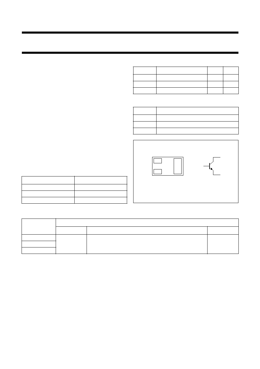
handbook, halfpage
MAM475
1
2
3
2
1
3
Bottom view
Fig.1 Simplified outline (SOT883) and symbol.
QUICK REFERENCE DATA
SYMBOL
PARAMETER
MAX.
UNIT
V
CEO
collector-emitter voltage
45
V
I
C
collector current (DC)
100
mA
I
CM
peak collector current
200
mA
ORDERING INFORMATION
TYPE NUMBER
PACKAGE
NAME
DESCRIPTION
VERSION
BC847AM
-
Leadless ultra small plastic package; 3 solder lands; body
1.0 x 0.6 x 0.5 mm
SOT883
BC847BM
BC847CM
2004 Mar 10
3
Philips Semiconductors
Product specification
NPN general purpose transistors
BC847M series
LIMITING VALUES
In accordance with the Absolute Maximum System (IEC 60134).
Notes
1. Refer to SOT883 standard mounting conditions (footprint), FR4 with 60
µ
m copper stripline.
2. Device mounted on a FR4 printed-circuit board, single-sided copper, mounting pad for collector 1 cm
2
.
THERMAL CHARACTERISTICS
Notes
1. Refer to SOT883 standard mounting conditions (footprint), FR4 with 60
µ
m copper stripline.
2. Device mounted on a FR4 printed-circuit board, single-sided copper, mounting pad for collector 1 cm
2
.
SYMBOL
PARAMETER
CONDITIONS
MIN.
MAX.
UNIT
V
CBO
collector-base voltage
open emitter
-
50
V
V
CEO
collector-emitter voltage
open base
-
45
V
V
EBO
emitter-base voltage
open collector
-
5
V
I
C
collector current (DC)
-
100
mA
I
CM
peak collector current
-
200
mA
I
BM
peak base current
-
100
mA
P
tot
total power dissipation
T
amb
25
°
C
note 1
-
250
mW
note 2
-
430
mW
T
stg
storage temperature
-
65
+150
°
C
T
j
junction temperature
-
150
°
C
T
amb
operating ambient temperature
-
65
+150
°
C
SYMBOL
PARAMETER
CONDITIONS
VALUE
UNIT
R
th(j-a)
thermal resistance from junction to ambient
in free air
note 1
500
K/W
note 2
290
K/W

2004 Mar 10
4
Philips Semiconductors
Product specification
NPN general purpose transistors
BC847M series
CHARACTERISTICS
T
amb
= 25
°
C unless otherwise specified.
Note
1. Pulse test: t
p
300
µ
s;
0.02.
SYMBOL
PARAMETER
CONDITIONS
MIN.
MAX.
UNIT
I
CBO
collector-base cut-off current
V
CB
= 30 V; I
E
= 0
-
15
nA
V
CB
= 30 V; I
E
= 0; T
j
= 150
°
C
-
5
µ
A
I
EBO
emitter-base cut-off current
V
EB
= 5 V; I
C
= 0
-
100
nA
h
FE
DC current gain
V
CE
= 5 V; I
C
= 2 mA
BC847AM
110
220
BC847BM
200
450
BC847CM
420
800
V
BE
base-emitter voltage
I
C
= 2 mA; V
CE
= 5 V
580
700
mV
I
C
= 10 mA; V
CE
= 5 V
-
770
mV
V
CEsat
collector-emitter saturation voltage
I
C
= 10 mA; I
B
= 0.5 mA
-
200
mV
I
C
= 100 mA; I
B
= 5 mA; note 1
-
400
mV
C
c
collector capacitance
I
E
= i
e
= 0; V
CB
= 10 V; f = 1 MHz
-
1.5
pF
f
T
transition frequency
V
CE
= 5 V; I
C
= 10 mA;
f = 100 MHz
100
-
MHz
F
noise figure
I
C
= 200
µ
A; V
CE
= 5 V;
R
S
= 2 k
; f = 1 kHz; B = 200 Hz
-
10
dB
2004 Mar 10
5
Philips Semiconductors
Product specification
NPN general purpose transistors
BC847M series
GRAPHICAL INFORMATION BC847AM
handbook, halfpage
0
100
200
300
400
MHC646
10
-
1
1
10
10
2
10
3
(1)
(2)
(3)
hFE
IC (mA)
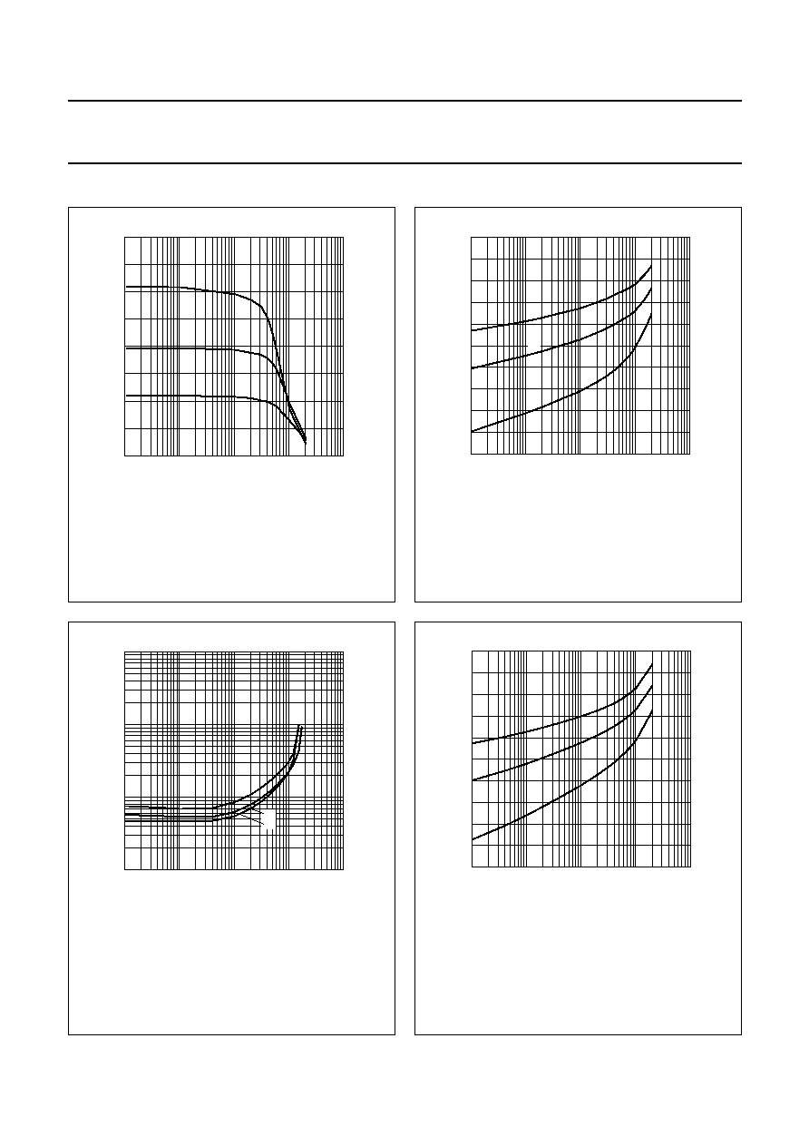
Fig.2 DC current gain; typical values.
V
CE
= 5 V.
(1) T
amb
= 150
°
C.
(2) T
amb
= 25
°
C.
(3) T
amb
=
-
55
°
C.
handbook, halfpage
200
1200
400
600
800
1000
MHC647
10
-
1
1
10
10
2
10
3
(1)
(2)
(3)
VBE
(mV)
IC (mA)
Fig.3
Base-emitter voltage as a function of
collector current; typical values.
V
CE
= 5 V.
(1) T
amb
=
-
55
°
C.
(2) T
amb
= 25
°
C.
(3) T
amb
= 150
°
C.
handbook, halfpage
10
4
10
3
10
2
10
MHC648
10
-
1
1
10
10
2
10
3
IC (mA)
VCEsat
(mV)
(1)
(2)
(3)
Fig.4
Collector-emitter saturation voltage as a
function of collector current; typical values.
I
C
/I
B
= 20.
(1) T
amb
= 150
°
C.
(2) T
amb
= 25
°
C.
(3) T
amb
=
-
55
°
C.
handbook, halfpage
200
1200
400
600
800
1000
MHC649
10
-
1
1
10
10
2
10
3
(1)
(2)
(3)
VBEsat
(mV)
IC (mA)
Fig.5
Base-emitter saturation voltage as a
function of collector current; typical values.
I
C
/I
B
= 10.
(1) T
amb
=
-
55
°
C.
(2) T
amb
= 25
°
C.
(3) T
amb
= 150
°
C.