Document Outline
- FEATURES
- PINNING
- APPLICATIONS
- DESCRIPTION
- MARKING
- LIMITING VALUES
- ELECTRICAL CHARACTERISTICS
- THERMAL CHARACTERISTICS
- GRAPHICAL DATA
- PACKAGE OUTLINE
- DEFINITIONS
DATA SHEET
Product specification
1999 Aug 05
DISCRETE SEMICONDUCTORS
BAT754 series
Schottky barrier (double) diodes
age
M3D088
1999 Aug 05
2
Philips Semiconductors
Product specification
Schottky barrier (double) diodes
BAT754 series
FEATURES
·
Very low forward voltage
·
Guard ring protected
·
Small plastic SMD package
·
Low diode capacitance.
APPLICATIONS
·
Ultra high-speed switching
·
Voltage clamping
·
Protection circuits
·
Blocking diodes
·
Low power consumption
applications, e.g. hand-held
applications.
DESCRIPTION
Planar Schottky barrier diodes
encapsulated in a SOT23 small
plastic SMD package. Low forward
voltage selection of the BAT54 series.
Single diodes and double diodes with
different pinning are available.
PINNING
PIN
BAT754
A
C
S
1
a
k
1
a
1
a
1
2
n.c.
k
2
a
2
k
2
3
k
a
1
, a
2
k
1
, k
2
k
1
, a
2
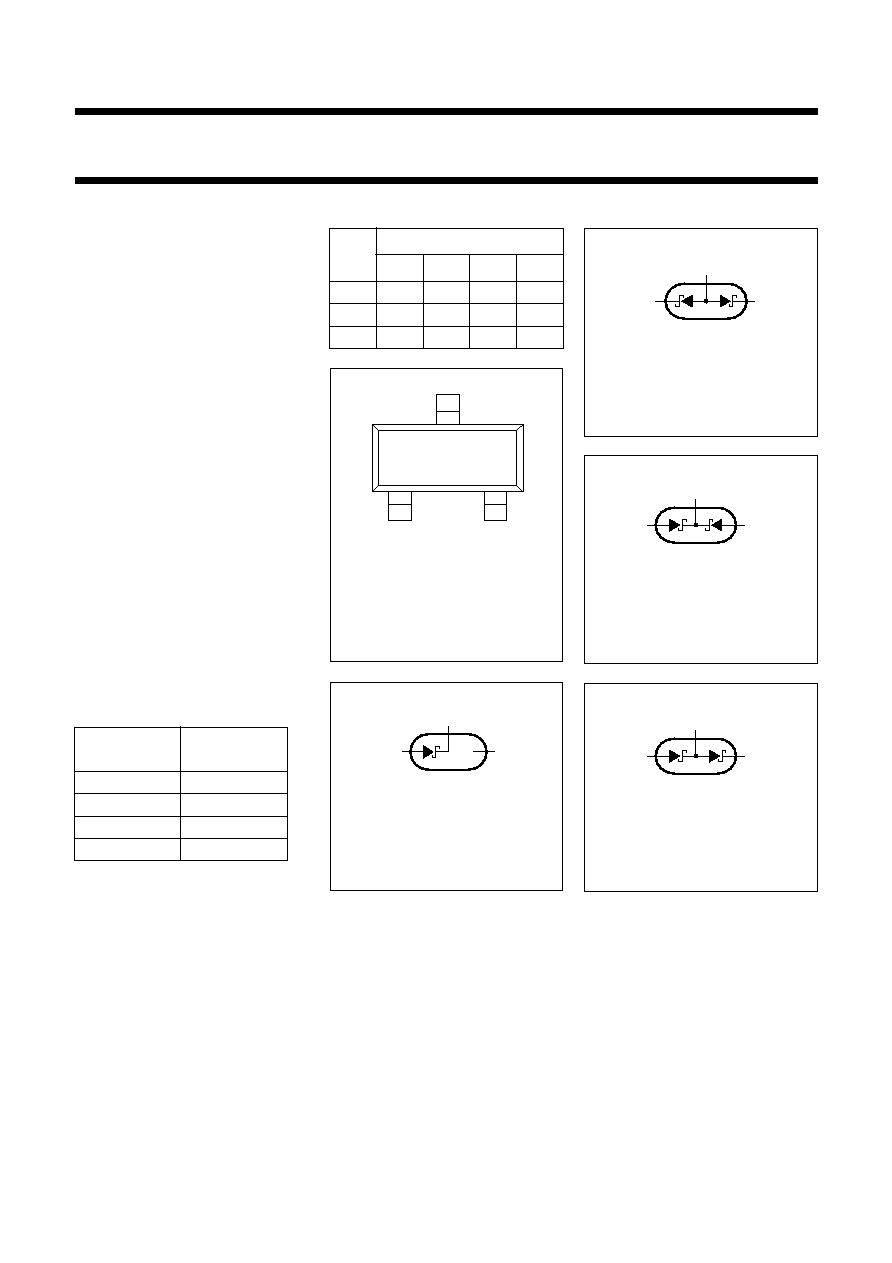
Fig.1
Simplified outline
(SOT23) and pin
configuration.
handbook, 2 columns
2
1
3
MGC421
Top view
Fig.2
BAT754 single diode
configuration (symbol).
3
1
2
n.c.
MLC357
Fig.3
BAT754A diode
configuration (symbol).
3
1
2
MLC360
Fig.4
BAT754C diode
configuration (symbol).
3
1
2
MLC359
Fig.5
BAT754S diode
configuration (symbol).
3
1
2
MLC358
MARKING
TYPE
NUMBER
MARKING
CODE
BAT754
2K
BAT754A
2L
BAT754C
2M
BAT754S
2N

1999 Aug 05
3
Philips Semiconductors
Product specification
Schottky barrier (double) diodes
BAT754 series
LIMITING VALUES
In accordance with the Absolute Maximum Rating System (IEC 134).
ELECTRICAL CHARACTERISTICS
T
amb
= 25
°
C unless otherwise specified.
Note
1. Pulse test: t
p
= 300
µ
s;
0.02.
THERMAL CHARACTERISTICS
Note
1. Refer to SOT23 standard mounting conditions.
SYMBOL
PARAMETER
CONDITIONS
MIN.
MAX.
UNIT
Per diode
V
R
continuous reverse voltage
-
30
V
I
F
continuous forward current
-
200
mA
I
FRM
repetitive peak forward current
t
p
1 s;
0.5
-
300
mA
I
FSM
non-repetitive peak forward current
t = 8.3 ms half sinewave;
JEDEC method
-
600
mA
T
stg
storage temperature
-
65
+150
°
C
T
j
junction temperature
-
125
°
C
T
amb
operating ambient temperature
-
65
+125
°
C
SYMBOL
PARAMETER
CONDITIONS
TYP.
MAX.
UNIT
Per diode
V
F
forward voltage
see Fig.6
I
F
= 0.1 mA
-
200
mV
I
F
= 1 mA
-
260
mV
I
F
= 10 mA
-
340
mV
I
F
= 30 mA
-
420
mV
I
F
= 100 mA
600
-
mV
I
R
reverse current
V
R
= 25 V; note 1; see Fig.7
-
2
µ
A
C
d
diode capacitance
f = 1 MHz; V
R
= 1 V; see Fig.8
-
10
pF
SYMBOL
PARAMETER
CONDITIONS
VALUE
UNIT
R
th j-a
thermal resistance from junction to
ambient
note 1
500
K/W
1999 Aug 05
4
Philips Semiconductors
Product specification
Schottky barrier (double) diodes
BAT754 series
GRAPHICAL DATA
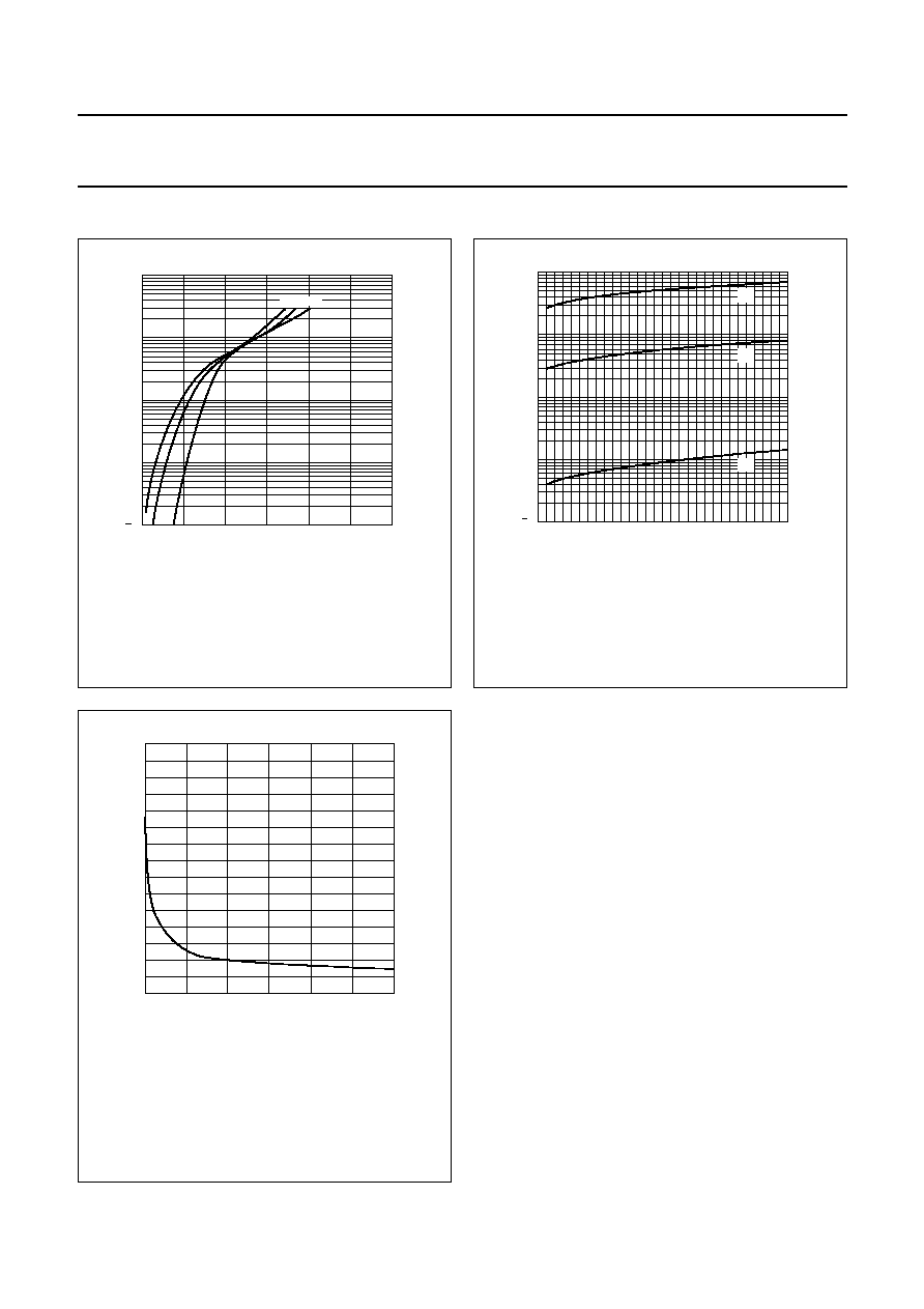
Fig.6
Forward current as a function of forward
voltage; typical values.
(1) T
amb
= 125
°
C.
(2) T
amb
= 85
°
C.
(3) T
amb
= 25
°
C.
handbook, halfpage
10
IF
VF (V)
3
10
(mA)
2
10
1
10
1
1.2
0.8
0.4
0
MSA892
(3)
(2)
(1)
(3)
(2)
(1)
Fig.7
Reverse current as a function of reverse
voltage; typical values.
(1) T
amb
= 125
°
C.
(2) T
amb
= 85
°
C.
(3) T
amb
= 25
°
C.
0
10
20
30
V (V)
R
10
3
I
R
(
µ
A)
10
2
10
1
10
1
(1)
(2)
(3)
MSA893
Fig.8
Diode capacitance as a function of reverse
voltage; typical values.
f = 1 MHz; T
amb
= 25
°
C.
0
10
20
30
0
5
10
15
V (V)
R
C d
(pF)
MSA891
1999 Aug 05
5
Philips Semiconductors
Product specification
Schottky barrier (double) diodes
BAT754 series
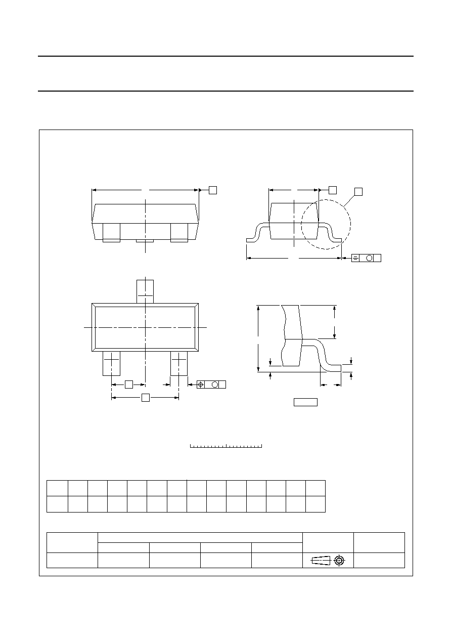
PACKAGE OUTLINE
UNIT
A
1
max.
b
p
c
D
E
e
1
H
E
L
p
Q
w
v
REFERENCES
OUTLINE
VERSION
EUROPEAN
PROJECTION
ISSUE DATE
97-02-28
IEC
JEDEC
EIAJ
mm
0.1
0.48
0.38
0.15
0.09
3.0
2.8
1.4
1.2
0.95
e
1.9
2.5
2.1
0.55
0.45
0.1
0.2
DIMENSIONS (mm are the original dimensions)
0.45
0.15
SOT23
bp
D
e1
e
A
A1
Lp
Q
detail X
HE
E
w
M
v
M
A
B
A
B
0
1
2 mm
scale
A
1.1
0.9
c
X
1
2
3
Plastic surface mounted package; 3 leads
SOT23