1
Variable Capacitance Diodes
MA2C840
Silicon epitaxial planar type
For AFC of UHF and VHF electronic tuner
I Features
· Super-small envelope (DO-34), allowing to insert into a 5 mm
pitch hole.
· Small series resistance r
D
· Large variable capcitance range
I Absolute Maximum Ratings T
a
= 25°C
Unit : mm
Parameter
Symbol
Rating
Unit
Reverse voltage (DC)
V
R
32
V
Peak forward current
V
RM
34
V
Junction temperature
T
j
150
°C
Storage temperature
T
stg
-55 to +150
°C
Parameter
Symbol
Conditions
Min
Typ
Max
Unit
Forward current (DC)
V
F
I
F
= 100 mA
1.1
V
Reverse current (DC)
I
R
V
R
= 30 V
10
nA
Reverse current (DC)
C
t
V
R
= 2 V, f = 1 MHz
10.5
16
pF
V
R
= 10 V, f = 1 MHz
3.3
5.7
Capacitance ratio
*
C
t(2V)
/C
t(10V)
2.5
3.4
C
t(6V)
/C
t(10V)
1.64
Series resistance
r
D
C
D
= 9 pF, f = 470 MHz
1.2
I Electrical Characteristics T
a
= 25°C
Note) 1
Rated input/output frequency: 470 MHz
2
* : C
t(2V)
/C
t(10V)
, C
t(6V)
/C
t(10V)
rank classification table
1 : Anode
2 : Cathode
JEDEC : DO-34
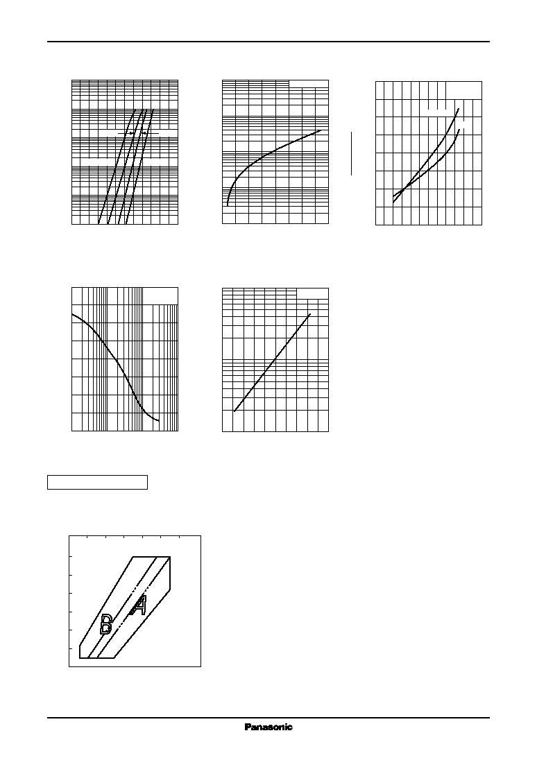
I Cathode Indication
1st Band
2nd Band
0.45 max.
1.75 max.
13 min.
0.2 max.
0.2 max.
13 min.
2.2
±
0.3
COLORED BAND
INDICATES
CATHODE
2
1
Class
A
B
M
1st band
Light Blue
Light Blue
Light Blue
2nd band
White
Green
Light Blue
Class
A
B
M
C
t(2V)
/C
t(10V)
2.5 to 3.0
2.8 to 3.4
2.8 to 3.4
C
t(6V)
/C
t(10V)
>1.64