ICs for FM/AM Tuner
s
Overview
The AN7273 and the AN7273S are the ICs designed
for Hi-Fi stereo tuner. They are functioned with stop signal
pin besides the AN7223S function.
s
Features
Ę
Level meter output (FMŁAM common use)
Ę
Stop signal output (for synthesizer tuner)
Ę
AM : including RF amplifier and high sensitivity
Ę
Low power consumption
Ę
Low shock noise level from function switch operation
Ę
Fewer external parts
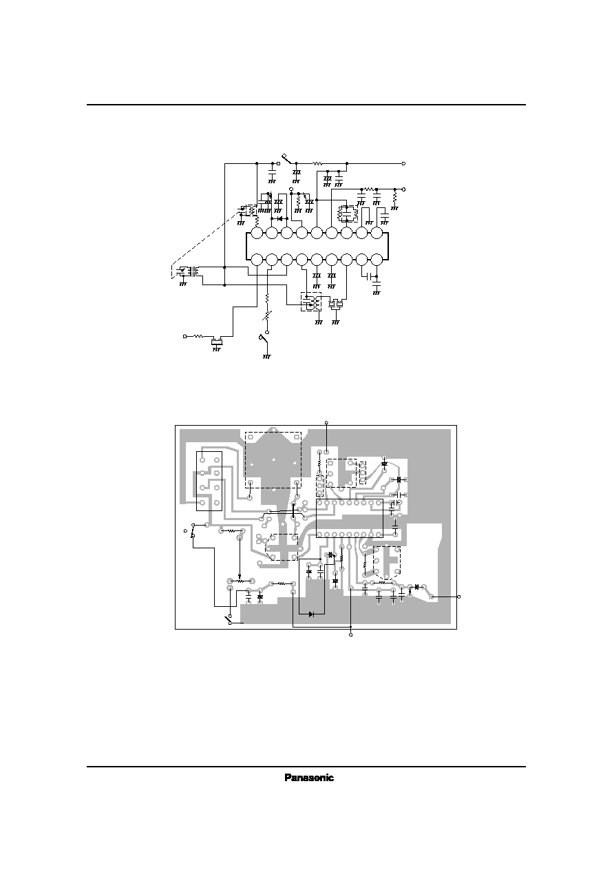
AN7273, AN7273S
AM Tuner, FM/AM IF Amplifier Circuit
8
9
1
7
4
3
5
18
6
2
10
11
15
13
16
17
14
12
AMŁFM
IF Amp.
FM IF
Amp.
FM
Quad. Det.
Mute Det.
AF Amp.
Mute or Shock
Noise Canceller
Level Meter
AM
Mixer
AM RF
Amp.
AM
L. Osc.
AGC
AM Det.
GND
V
CC (AM)
V
CC
V
REF
s
Block Diagram
1
2
3
4
5
6
7
8
3 ~ 15░
7.62
▒
0.25
0.3
+ 0.1
Ł 0.025
3.8
▒
0.25
(3.45)
0.51min.
2.54
1.2
▒
0.25
0.5
▒
0.1
Unit : mm
6.3
▒
0.25
18
17
16
15
14
13
12
11
21.7
▒
0.3
9
10
AN7273
18-Lead DIP Package (DIP018-P-0300E)
1.3
0.4
▒
0.25
1.27
0.1
0.3
1.2
▒
0.3
0.65
0.15
AN7273S
12.6
▒
0.3
7.7
▒
0.3
5.4
▒
0.3
Unit : mm
18-Lead SOP Package (SOP018-P-0300)
1
9
18
10

AN7273, AN7273S
ICs for FM/AMTuner
Pin No.
Pin Name
1
2
3
4
5
6
7
8
9
FM IF Input
AM Supply/Mute Adjustment
AM RF Input
AM Mixer Output
AGC Output (2)
AGC Output (1)
AM IF Input
IF By-pass
IF By-pass
s
Pin Descriptions
Pin No.
Pin Name
10
11
12
13
14
15
16
17
18
AM Detection Output
GND
FM Detection Coil
AF Output
V
CC
Level Meter Output
AFC Output
Reference Voltage
Local Oscillation Coil
Parameter
Symbol
Rating
Unit
P
D
T
opr
T
csg
V
CC
I
CC
AN7273
AN7273S
AN7273
AN7273S
AN7273
AN7273S
Power Dissipation
Operating Ambient Temperature
Storage Temperature
Supply Voltage
Supply Current
mW
░C
░C
V
mA
14.4
30
317 *
1
210 *
2
Ł20 ~ + 75
Ł20 ~ + 75
Ł55 ~ + 150
Ł55 ~ + 125
*1 Ta = 25░C, *2 Ta = 75░C
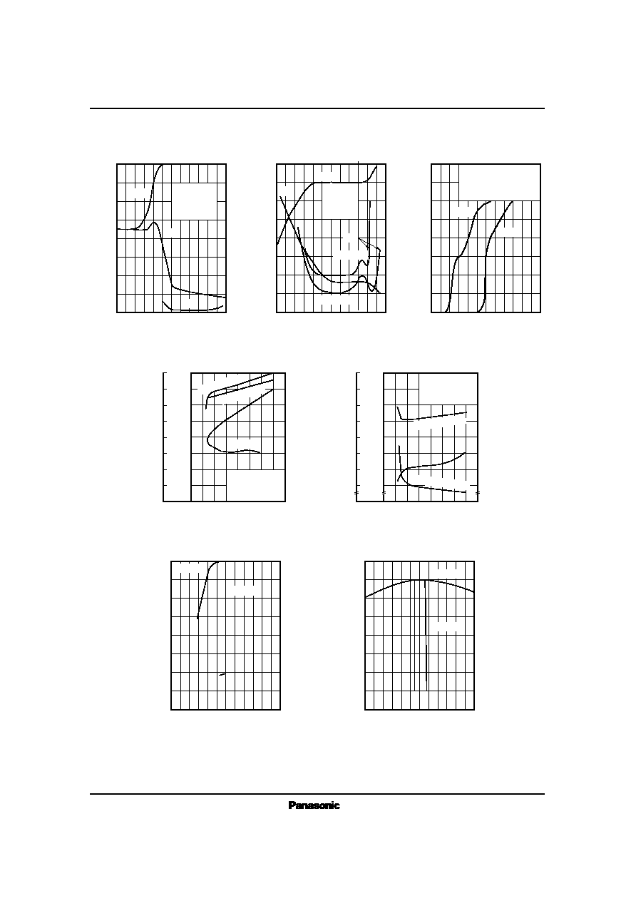
s
Absolute Maximum Ratings
(Ta=25░C)
DC measurement
V
i
=80dB
Ą
Input at V
O
= Ł3dB
Input at V
O
=more than Ł20dB
V
i
=70dB
Ą
V
i
=100dB
Ą
DC measurement
V
i
=80dB
Ą
Input at V
O
=10mV
V
i
= Ł10dB
Ą
V
i
=80dB
Ą
Parameter
Symbol
Condition
min.
typ.
max.
Unit
s
Electrical Characteristics
(V
CC
= 5V, Ta= 25░C)
I
tot
V
O
V
i (lim)
V
i (Mute)
V
15Ł11
V
15Ł11
I
tot
V
O
S
max.
V
15Ł11
V
15Ł11
9
75
43.5
55
0.61
1.14
8
60
4
0
1.12
14
100
46
64
0.8
1.26
13
80
9.5
1.25
20
125
49.5
73
1.1
1.42
19
100
15
130
1.38
mA
mV
dB
Ą
dB
Ą
V
V
mA
mA
dB
Ą
mV
V
Total Circuit Current
Demodulation Output Level
Limiting Sensitivity
Muting Sensitivity
Level Meter Driving Output (1)
Level Meter Driving Output (2)
Total Circuit Current
Detection Output Level
Max. Sensitivity
Level Meter Driving Output (1)
Level Meter Driving Output (2)
Note) Unless otherwise specified, f
i
=10.7MHz, Mod.
= 22.5kHz, f
m
= 400Hz (FM)
f
i
=1MHz, Mod.
= 30%, f
m
= 400Hz (AM)
FM
AM
Parameter
Symbol
Range
s
Recommended Operating Range
(Ta = 25░C)
Operating Supply Voltage Range
V
CC (opr)
3 ~ 12V

ICs for FM/AMTuner
AN7273, AN7273S
Symbol
T
1
Use, Freq.
Type No.
Maker
Connection Diagram Number of Turns Tuning Cap.
Unloaded Q
T
2
T
3
Matsushita
Matsushita
Matsushita
100pF
--
1500pF
90
▒
20%
95
▒
20%
60
▒
30%
FM
Quad. Coil
10.7MHz
AM MW
Osc. Coil
AM Mix.
Output
455kHz
ELLŁ
7S754
ELFŁ
7S752A
s
Coil Specifications
1 Ł 2 8T
2 Ł 3 5T
4 Ł 6 3T
1 Ł 2 4T
2 Ł 3 125T
4 Ł 6 7T
3 Ł 2 35T
6 Ł 4 10T
2 Ł 1 19T
EIAŁ
7S802A
4
6
2
1
3
4
6
2
3
1
4
6
2
3
1
Toko
CF
1
Symbol
Maker
Band Width
Loss
s
Ceramic Filter Specification
455kHz
Use
Type No.
Center Freq.
AM IF
CFM2Ł 455B
7kHz (Ł6dB)
2.6dB