s
Overview
The AN7233SH is an IC for tuner of 1.5V headphone
stereo. It incorporates AM tuner + FM IF + FM detector +
FM MPX and has been provided with the station detec-
tion function and IF count output function required to sup-
port DTS, and the AM IF output function required to sup-
port AM stereo. It is included in the 28-lead SSOP pack-
age with 0.5mm pitch.
s
Features
·
Low voltage operation : V
CC
=1.0V or more
·
AM tuner/FM IF + FM detection + FM MPX : one chip
·
DTS supported
·
AM stereo support possible
·
Adjustable sensitivity for station detection
·
Small package
s
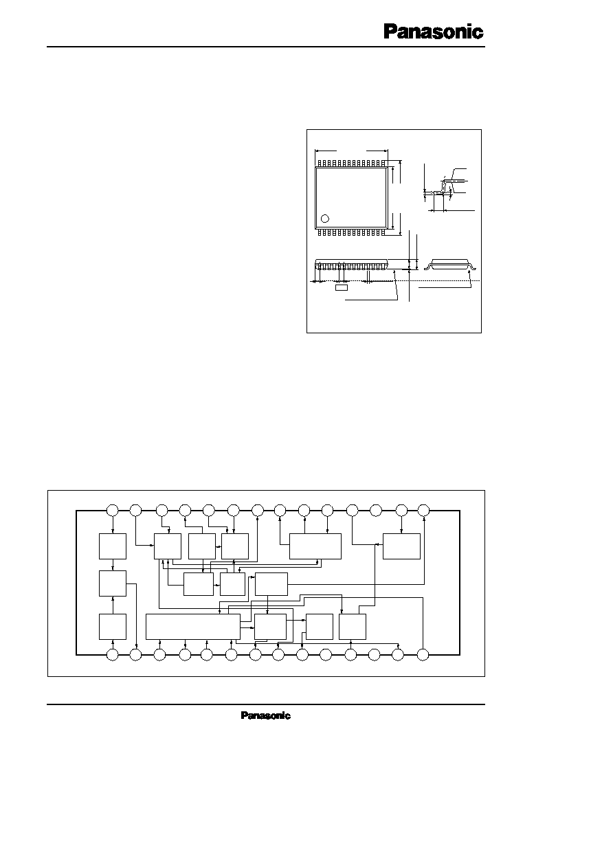
Block Diagram
ICs for FM/AM Tuner
AN7233SH
FM/AM Tuner for 1.5V Headphone Stereo
Unit : mm
28
15
1
14
(0.65)
0.50
0.2
+ 0.10
0.05
1.55max.
1.20
±
0.20
28-lead SSOP package (SSOP028-P-0300)
7.80
±
0.20
8.10
±
0.30
6.10
±
0.20
0.5
±
0.20
SEATING PLANE
0 ~10°
0.15
+ 0.10
0.05
SEATING PLANE
0.10
±
0.10
AM Det.
AGC
PC
AM
Osc
AM
Mix.
AM
RF
IF
LEVEL
Det.
SD
V
CC
GND
FM
Det.
ST Ind.
VCO
LPF
MPX
SW
AM AF
Buffer
1
2
3
4
5
6
7
8
9
10
11
12
13
14
28
27
26
25
24
23
22
21
20
19
18
17
16
15
Freq.
Divider

AN7233SH
ICs for FM/AM Tuner
s
Absolute Maximum Ratings
(Ta=25°C)
V
CC
I
CC
P
D
T
opr
T
stg
Supply Voltage
Supply Current
Power Dissipation
Operating Ambient Temperature
Storage Temperature
V
mA
mW
°C
°C
Parameter
Symbol
Rating
Unit
7.0
10
70
20 ~ + 75
55 ~ + 125
Parameter
Symbol
Range
s
Recommended Operating Range
(Ta=25°C)
Operating Supply Voltage Range
V
CC
1.0V ~ 2.0V
Parameter
Symbol
Condition
min.
typ.
max.
Unit
s
Electrical Characteristics
(V
CC
=1.2V, Ta= 25°C
±
2°C)
Total Circuit Current
Output Voltage
Limiting Sensitivity
S/N Ratio
THD
mA
mV
dB
µ
dB
%
No signals (under VCO operating)
V
i
for V
O
= 3dB
I
tot (FM)
V
O (FM)
V
i (lim)
IF Buffer Output 2
LED ON Sensitivity
LED Decreased Voltage ON Sensitivity
IF Buffer Output 1
V
CC
=1.0V, No modulation REQ OFF
V
IN
= 80dB
µ
, No modulation
V
CC
=1.1V, No modulation REQ OFF
V
i (FMLED1)
V
i (FMLED2)
V
OIF1 (FM)
5.5
26
38
55
7.5
44
45
9.5
61
48
1.4
48
48
55
58
48
61
69
86
dB
µ
dB
µ
mVrms
Note) FM : f = 10.7MHz, Df = 22.5kHz, f
m
= 1kHz, V
IN
= 80dB
µ
, AM : f = 1MHz, Mod. = 30%, f
m
= 1kHz, V
IN
= 50dB
µ
MPX : f = 10.7MHz, Df = 75kHz (L+ R90%, Pilot90%), f
m
= 1kHz, V
IN
= 80dB
µ
FM
S/N (FM)
THD (FM)
AM
S/N (AM)
THD (AM)
V
CC
=1.1 V, No modulation REQ OFF
MPX
THD
(STEREO)
V
P (ON)
V
P (OFF)
V
OIF2 (FM)
V
CC
=1.0V, V
IN
= 80dB
µ
,
No modulation
mVrms
19
Total Circuit Current
Output Voltage
Weak Input Detection Output Voltage
S/N Ratio
THD
LED ON Sensitivity
Itot
(AM)
V
O (AM)
V
O (AMMIN)
mA
mV
mV
dB
µ
%
dB
3.0
21
12
36
16
5.0
31
24
23
7.0
41
5.0
30
V
IN
= 26dB
µ
V
i (AMLED)
IF Buffer Output 1
V
OIF1 (AM)
V
CC
=1.1V, V
IN
= 45dB
µ
,
No modulation
mVrms
29
43
57
IF Buffer Output 2
V
OIF2 (AM)
V
CC
=1.0V, V
IN
= 45dB
µ
,
No modulation
mVrms
15
AM IF Output Voltage
V
O (AM IF)
mVrms
15
30
60
V
IN
= 50dB
µ
, No modulation
Channel Balance
Separation
THD (Stereo)
Stereo LED ON Level
Stereo LED OFF Level
CB
Sep.
dB
dB
%
%
%
2
22
0.8
0
35
4.8
1.9
2
5.0
7.0
Monaural Df= 75kHz
MPX Portion only L + R= 30%
L + R= 90%, Pilot= 10%
Pilot only
Pilot only

ICs for FM/AM Tuner
AN7233SH
s
Pin Descriptions
Pin No.
Pin Name
1
2
3
4
5
6
7
8
9
10
11
12
13
14
AM RF Amp. Input
AM Mixer Output
Supply Pin for IF Input Portion/AMOSC Section
AM AGC
AM IF Amp. Input
FM IF Amp. Input
SD LED ON Level Adjustment
Stereo LED Drive/AMIF Output Pin
SD LED Drive Pin
Supply Pin
Phase-Shifter Pin for FM Detection
GND Pin
Output for FM/AM IF Count
IF Count Control Pin
Pin No.
Pin Name
15
16
17
18
19
20
21
22
23
24
25
26
27
28
AM Detection Pin
AM AF Amp. Input Pin
Oscillation Prevention Capacitor Pin
FM/AM Detection Output Pin
MPX Input Pin
Rch Output Pin
Lch Output Pin
AM/FM Changeover/19kHz Output Pin
Loop Filter Pin 1 for PLL
Loop Filter Pin 2 for PLL
CR Connecting Pin for VCO
Low Pass Filter Pin 1 for Pilot Detection
Low Pass Filter Pin 2 for Forced
MONO/Pilot Detection
AM Local Oscillation Coil Pin
Divider
AM Det.
AGC
PC
AM
OSC
AM
Mix.
AM
RF
IF
LEVEL
Det.
SD
FM
Det.
ST
Ind.
VCO
LPF
MPX
SW
AM AF
Buffer
1
2
3
6
7
8
9
10
11
12
13
14
4
5
MPX Fillter
0.022
µ
F
24k
Freg.
Counter
8
2
0
0
p
F
+
4.7
µ
F
4.7
µ
F
8
2
0
0
p
F
1
0
0
k
1
0
0
k
V
V
CC
0
.
0
4
7
µ
F
STEREO
SG
0
.
0
2
2
µ
F
8
2
p
F
0.33
µ
F
6
.
2
k
6
.
2
k
+
0.22
µ
F
AM
MONO.
+
0.1
µ
F
1
k
6
8
0
p
F
1
5
k
1
0
k
+
1
µ
F
10pF
V1
4
7
0
k
KV1281
REQ
0
.
0
1
µ
F
0
.
0
3
3
µ
F
2
S
C
1
3
5
9
1
0
0
2
S
C
1
3
5
9
3V
RF
Voltage
Meter
4
.
3
k
1
.
8
k
2
S
K
1
9
2
A
3
9
0
5
1
0
k
5
1
0
k
C
D
A
1
0
.
7
M
G
3
9
p
F
S
D
0
.
0
1
µ
F
S
T
0.022
µ
F
+
0
.
0
1
µ
F
5
1
.
7
k
IF Count
2
2
0
k
2
8
0
50
+
4
.
7
µ
F
S
F
E
1
0
.
7
M
A
5
S
F
U
4
5
0
3
1
4
1
m
H
FMSG
AMSG
50
5
0
0.022
µ
F
AMIF
Audio
Analazer
RLO2U8 M
Tuning Electric Current
28
27
26
25
24
23
22
21
20
19
18
17
16
15
+
4
.
7
k
1
k
1
k
V
3.3k
270pF
s
Application Circuit