ICs for FM/AM Tuner
s
Overview
The AN7223 is an IC designed for high-class radio cas-
sette recorder with multifunctioned FM/AM IF system.
s
Features
Ę
Wide operating supply voltage range : V
CC
= 2.8V~12V
Ę
Incorporating both FM and AM detectors
Ę
Incorporating a level indicator output
(FM/AM common use)
Ę
AM : High sensitivity,including RF amplifier
Ę
Low power consumption
Ę
Muting control
Ę
AFC control
Ę
Fewer external parts
Ę
High stability on both AM and FM
Ę
Low shock noise level from function switch operation
Ę
SW band available (f= 30MHz)
AN7223
AM Tuner, FM/AM IF Amplifier Circuit for Radio Cassette Recorder
1
2
3
4
5
6
7
8
9
21.7
▒
0.3
1.2
▒
0.25
3 ~ 15░
Unit : mm
6.3
▒
0.25
0.5
▒
0.1
2.54
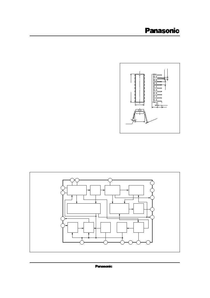
18-Lead DIP Package (DIP018-P-0300E)
(3.45)
7.62
▒
0.25
0.3
+ 0.1
Ł 0.25
18
17
16
15
14
13
12
11
10
0.51min.
3.8
▒
0.25
8
9
12
5
18
6
2
10
11
15
13
16
17
14
1
7
4
3
AM/FM
IF Amp.
FM IF
Amp.
FM
Quad. Det.
Mute Det.
Level Meter
Mute or
Shock Noise
Canceller
AF
Amp.
AM RF
Amp.
AM
Mixer
AM
L Osc.
AGC
AM
Det.
GND
V
CC
(AM)
V
CC
s
Block Diagram

ICs for FM/AM Tuner
AN7223
Pin No.
Pin Name
1
2
3
4
5
6
7
8
9
FM IF Amp. Input
V
CC
(AM)
AM RF Amp. Input
AM Mixer Output
AGC Output (2)
AGC Output (1)
AM IF Amp. Input
IF By-pass
IF By-pass
s
Pin Descriptions
Pin No.
Pin Name
10
11
12
13
14
15
16
17
18
AM Detection Output
GND
FM Detector Coil
AF Output
V
CC
Level Meter Output
AFC Output
Reference Voltage
Local Oscillation
V
CC
P
D
T
opr
T
stg
Supply Voltage
Power Dissipation
Operating Ambient Temperature
Storage Temperature
V
mW
░C
░C
Parameter
Symbol
Rating
Unit
14.4
317
Ł20 ~ + 75
Ł55 ~ + 150
s
Absolute Maximum Ratings
(Ta=25░C)
V
i
= 80dB
Ą
, f=10.7MHz,
f
dev.
= 22.5kHz, f
m
= 400Hz
Input at
O
= Ł3dB
Input at
O
= less than Ł20dB
V
i
= 50dB
Ą
, f=10.7MHz,
f
dev.
= 22.5kHz, f
m
= 400Hz
V
i
= 80dB
Ą
, f= 10.7MHz,
f
dev.
= 22.5kHz, f
m
= 400Hz
V
i
= 80dB
Ą
, f= 1MHz,
Mod.= 30%, f
m
= 400Hz
Input at
O
= 10mV
V
i
= Ł10dB
Ą
, f= 1MHz,
Mod.= 30%, f
m
= 400Hz
V
i
= 80dB
Ą
, f= 1MHz,
Mod.= 30%, f
m
= 400Hz
Parameter
Symbol
Condition
min.
typ.
max.
Unit
Total Circuit Current
Demodulation Output Level
Limiting Sensitivity
Muting Sensitivity
Signal Meter Driving
Output 1
Signal Meter Driving
Output 2
Total Circuit Current
Detection Output Level
Max.Sensitivity
Signal Meter Driving
Output 1
Signal Meter Driving
Output 2
I
tot
O (FM)
V
i (lim)
V
i
(mute)
V
15
V
15
I
tot
O (AM)
S
max.
V
15
V
15
9
75
41.5
45
120
1.14
8
60
4.5
0
1.12
FM
AM
mA
mV
dB
Ą
dB
Ą
mV
V
mA
mV
dB
Ą
mV
V
(DC measurement)
(DC measurement)
14
100
44.5
50
600
1.26
13
80
9.5
1.25
20
125
47.5
59
1150
1.42
19
100
12.5
130
1.38
s
Electrical Characteristics
(V
CC
=5V, Ta= 25░C)
AN7223
ICs for FM/AM Tuner
18
17
16
15
14
13
12
11
10
1
2
3
4
5
6
7
8
9
Ł
+
Ł
+
Ł
+
Ł
+
Ł
+
Ł
+
Ł
+
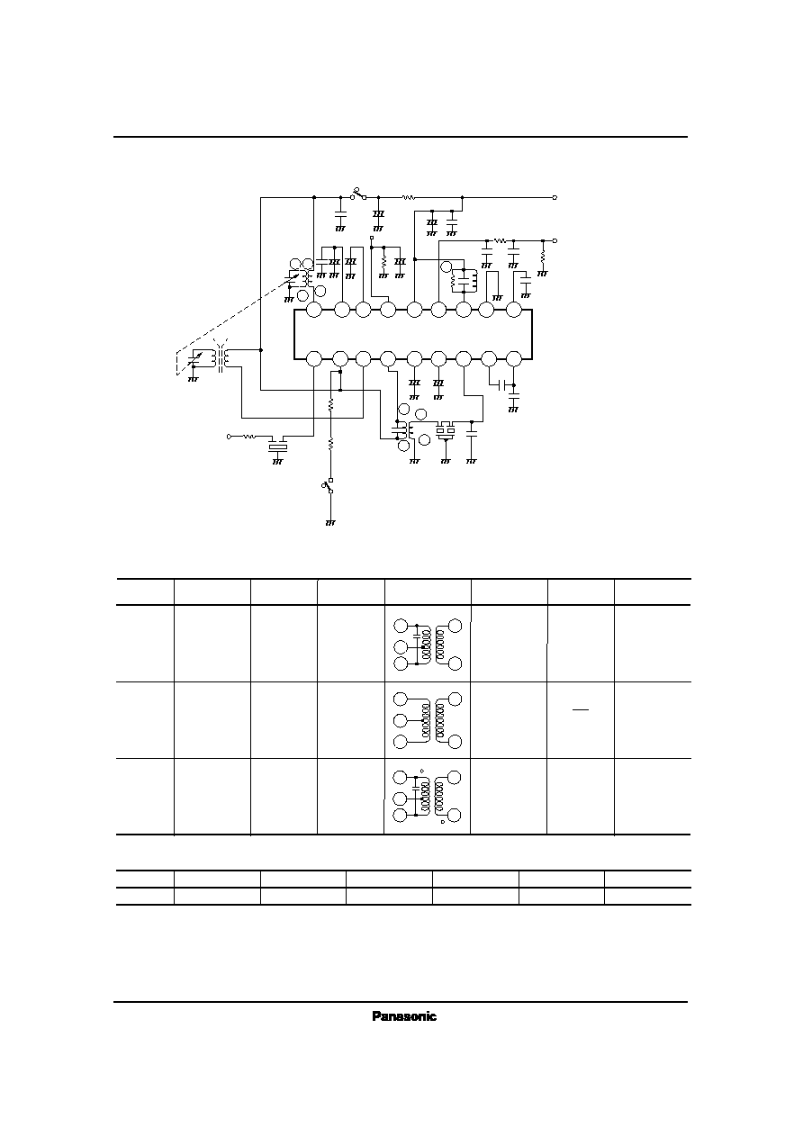
AN7223
V
CC
(5V)
0.022
Ą
F
5
.
1
k
1
0
Ą
F
2
2
Ą
F
4
1
6
3
T
2
4
7
p
F
0
.
0
2
2
Ą
F
0
.
0
2
2
Ą
F
AM
FM
47
1
0
0
Ą
F
V15
4
7
Ą
F
1
0
0
Ą
F
470
2
.
2
k
1
T
1
0
.
0
0
4
7
Ą
F
0
.
0
1
Ą
F
0.022
Ą
F
V
O
(FM.AM)
2
7
k
to Front End
OFF
Mute
ON
2
.
1
k
1
0
0
Ą
F
1
0
k
6
1
T
3
4
3
4
.
7
Ą
F
47pF
0
.
0
2
Ą
F
0.02
Ą
F
Symbol
T
1
Use, Freq
Type No.
Maker
Connection
Diagram
Number of
Turns
Tuning Cap.
Unloaded Q
T
2
T
3
MATSUSHITA
MATSUSHITA
MATSUSHITA
100pF
1500pF
90
▒
20%
95
▒
20%
60
▒
30%
FM
Quad. Coil
10.7MHz
AM MW
Osc. Coil
AM Mix.
Output
455kHz
ELLŁ
7S754
EIFŁ
7S752A
s
Coil Specifications
1 Ł 2 8T
2 Ł 3 5T
4 Ł 6 3T
1 Ł 2 4T
2 Ł 3 125T
4 Ł 6 7T
3 Ł 2 35T
6 Ł 4 10T
2 Ł 1 19T
EIAŁ
7S802A
6
4
6
2
3
1
4
6
2
3
1
4
6
2
3
1
TOKO
CF
1
Symbol
Maker
Band Width
Loss
s
Ceramic Filter Specification
455kHz
Use
Type No.
Center Freq.
AM IF
CFM2 Ł 455B
7kHz (Ł6dB)
2.6dB
s
Application Circuit