s Overview
The AN2458SH is a color encoder IC for NTSC/
PAL-compatible CCD video camera. It outputs chro-
ma signal after modulation of inputted RÙY and BÙY
color difference signals with subcarrier signals.
s Features
ñ Compatible with NTSC and PAL
ñ Carrier leak adjustment available
ñ Built-in blanking circuit
ñ Color phase adjustment available
ñ Improved temperature characteristics of color phase
shift (within
Ý
5¯C)
AN2458SH
Color Encoder IC (NTSC/PAL) for CCD Video Camera
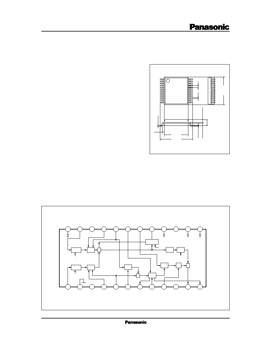
s Block Diagrams
5.5
Ý
0.3
7.5
Ý
0.3
(0.5)
0.1
Ý
0.1
0.15
0.65
Ý
0.1
1.5
Ý
0.2
+
0.1
Ù 0.05
0.65
Ý
0.1
6.5
Ý
0.3
0.5
0.2
Ý
0.1
1
12
24
13
Unit:mm
24-Pin SSOP Package (SSOP024-P-0300)
24
23
22
21
20
19
18
17
16
15
14
13
1
2
3
4
5
6
7
8
9
10
11
12
BÙY IN
GND
BÙY
OFF
BÙY
SC
90.
ADJ
HUE.C
HUE.
CR
BURST
LEVEL
NC
CHROMA
OUT
HUE.R
HUE
MOD
GC
BLK
Lim.
DC Cont.
CP2
BLK
V
CC
CP2
NC
V
CC
CP2. IN
BLK. IN
DC.
Cont. C
BF IN
HUE
Cont.
RÙY SC
RÙY
OFF
RÙY IN
V
REF
V
REF
NC
MOD
Clamp
Clamp
MOD
CP2
NC
GC
+
+
+
BLK

I
CC
V
5
V
CC
=4.8V, V
REF
=1.8V
V
CC
=4.8V, V
REF
=1.8V
diffrence from V
REF
1.8
2.3
2.8
V
V
11
V
CC
=4.8V, V
REF
=1.8V
Terminal voltage Pin11
Supply current
Terminal voltage Pin5
12.0
Ù100
16.0
0
20.0
100
mA
mV
Parameter
min
Condition
typ
max
Unit
Symbol
V
TH (CP2Ù1)
V
CC
=4.8V, V
REF
=1.8V
2.0
2.4
2.8
V
V
TH (CP2Ù2)
V
CC
=4.8V, V
REF
=1.8V
CP2 threshold 2
CP2 threshold 1
1.5
1.8
2.1
V
1.9
2.2
2.5
V
V
TH (BLK)
V
CC
=4.8V, V
REF
=1.8V
BLK threshold
V
20
V
CC
=4.8V, V
REF
=1.8V
diffrence from V
REF
Terminal voltage Pin20
Ù100
0
100
mV
G
V1
V
CC
=4.8V, V
REF
=1.8V
250mV
PÙP
input
RÙY GAIN
480
600
720
mV
PÙP
G
V2
V
CC
=4.8V, V
REF
=1.8V
250mV
PÙP
input
BÙY GAIN
Ù7.0
Ù5.5
Ù3.5
dB
G
V3
V
CC
=4.8V, V
REF
=1.8V
600mV
PÙP
input
CHROMA CLIP
0.5
3.0
4.5
dB
G
V4
V
CC
=4.8V, V
REF
=1.8V
250mV
PÙP
input
BLK=3V
OP
BLK CONTROL
300
600
900
mV
PÙP
G
V5
V
CC
=4.8V, V
REF
=1.8V
V
9
=V
REF
BURST GC (1)
290
350
430
mV
PÙP
G
V6
V
CC
=4.8V, V
REF
=1.8V
V
9
=V
REF
Ý
0.5V
BURST GC (2)
1.5
3.0
4.5
dB
G
V7
V
CC
=4.8V, V
REF
=1.8V
V
9
=V
REF
Ù0.5V
BURST GC (3)
Ù6.0
Ù4.5
Ù2.5
dB
1
V
CC
=4.8V, V
REF
=1.8V
V
19
=V
REF
+0.5V
BURST PHASE (1)
Ù45
Ù30
Ù15
deg
2
V
CC
=4.8V, V
REF
=1.8V
V
19
=V
REF
Ù0.5V
BURST PHASE (2)
0
15
30
deg
s Electrical Characteristics (Ta=25
Ý
2¯C)
Parameter
Symbol
Rating
Unit
V
CC
I
CC
P
D
T
opr
T
stg
25
120
Ù20 to +75
Ù55 to +125
Supply voltage
Supply current
Power dissipation
Operating ambient temperature
Note 1)
Storage temperature
Note 1)
5.5
V
mW
mA
¯C
¯C
Note 1) Ta=25¯C except operating ambient temperature and storage temperature.
s Absolute Maximum Ratings
Parameter
Symbol
Range
Operating supply voltage range
V
CC
4.6V to 5.0V
s Recommended Operating Range (Ta=25¯C)
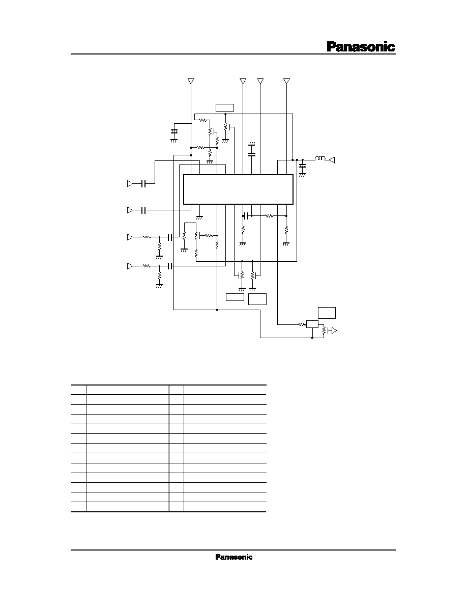
s Application Circuit
Color difference (BÙY) input
GND
N. C.
Subcarrier (0¯) OFF
Pin No.
1
2
3
4
Pin name
Clamp pulse input
V
CC
(4.8V typ.)
N. C.
Blanking pulse input
13
14
15
16
Subcarrier(0¯) input
5
DC playback capacitor
17
90¯adjustment
6
Burst flag input
18
Phase-shift capacitor
7
Phase adjustment
19
Phase-shift capacitor
8
Subcarrier (90¯/270¯) input
20
Burst amplitude adjustment
9
Subcarrier (90¯/270¯) OFF
21
Phase-shift resistors
12
V
REF
(1.8V typ.)
24
N. C.
10
N. C.
22
Chroma plus burst output
11
Color difference (RÙY) input
23
Pin name
Pin No.
s Pin Descriptions
24
23
22
21 20 19 18 17 16 15
14
13
1
2
3
4
5
6
7
8
9
10
11
12
AN2458SH
1k
*10pF
10kB
6400
1
k
27k
10k
0.001
ç
F
1500
6800
6800
0.001
ç
F
1500
SC0¯IN
SC90¯IN
BÙYsig.IN
RÙYsig.IN
0.22
ç
F
0.22
ç
F
50kB
50kB
90.Adj.
Burst
Level
Chroma
Level
BPF
1k
1k
CHROMA
OUT
22
ç
H
100
ç
F 16.3V
V
CC
(typ.4.8V)
+
0.047
ç
F
50kB
6400
10k
1k
10kB
27k
47
ç
F
16.3V
V
REF
(typ.1.8V)
BF (Burst Flag) IN
BLK (BLan King) IN
CP2 (Clamp Pulse) IN
+
22
k
22
k
HUE
* The phase-shift capacitor is typically
10 pF for both NTSC and PAL.