©
Semiconductor Components Industries, LLC, 2004
March, 2004 - Rev. 4
1
Publication Order Number:
MMT05A230T3/D
MMT05A230T3,
MMT05A260T3,
MMT05A310T3
Preferred Devices
Thyristor Surge Protectors
High Voltage Bidirectional TSPD
These Thyristor Surge Protective devices (TSPD) prevent
overvoltage damage to sensitive circuits by lightning, induction and
power line crossings. They are breakover-triggered crowbar
protectors. Turn-off occurs when the surge current falls below the
holding current value.
Secondary protection applications for electronic telecom equipment
at customer premises.
·
High Surge Current Capability: 50 Amps 10 x 1000
µ
sec; for
Controlled Temperature Environments in the SMA package
·
The MMT05A230T3 Series is used to help equipment meet various
regulatory requirements including: Telcordia 1089, ITU K.20 &
K.21, IEC 950 and FCC Part 68
·
Bidirectional Protection in a Single Device
·
Little Change of Voltage Limit with Transient Amplitude or Rate
·
Freedom from Wearout Mechanisms Present in Non-Semiconductor
Devices
·
Fail-Safe, Shorts When Overstressed, Preventing Continued
Unprotected Operation
·
Surface Mount Technology (SMT)
·
Indicates UL Registered - File #E210057
·
Device Marking: MMT05A230T3: PBF; MMT05A260T3: PBG;
MMT05A310T3: PBJ
MAXIMUM RATINGS
(T
J
= 25
°
C unless otherwise noted)
Rating
Symbol
Value
Unit
Off-State Voltage - Maximum
MMT05A230T3
MMT05A260T3
MMT05A310T3
V
DM
"
170
"
200
"
270
Volts
Maximum Pulse Surge Short Circuit
Current Non-Repetitive
Double Exponential Decay Waveform
(Notes 1 and 2)
8 x 20
µ
sec
10 x 160
µ
sec
10 x 560
µ
sec
10 x 1000
µ
sec
I
PPS1
I
PPS2
I
PPS3
I
PPS4
"
150
"
100
"
70
"
50
A(pk)
Maximum Non-Repetitive Rate of
Change of On-State Current Double
Exponential Waveform,
I
PK
= 50 A, P
W
= 15
m
s
di/dt
"
100
A/
µ
s
1. Allow cooling before testing second polarity.
2. Measured under pulse conditions to reduce heating.
BIDIRECTIONAL TSPD
50 AMP SURGE
265 thru 365 VOLTS
Preferred devices are recommended choices for future use
and best overall value.
Device
Package
Shipping
ORDERING INFORMATION
MMT05A230T3
SMA
12 mm Tape and Reel
(5 K/Reel)
MMT05A260T3
SMA
12 mm Tape and Reel
(5 K/Reel)
MMT05A310T3
SMA
12 mm Tape and Reel
(5 K/Reel)
MT1
MT2
SMA
(No Polarity)
CASE 403D
xxx
= Specific Device Code
A
= Assembly Location
Y
= Year
W
= Work Week
MARKING DIAGRAM
xxx
AYW
http://onsemi.com
For information on tape and reel specifications,
including part orientation and tape sizes, please
refer to our Tape and Reel Packaging Specification
Brochure, BRD8011/D.

MMT05A230T3, MMT05A260T3, MMT05A310T3
http://onsemi.com
2
THERMAL CHARACTERISTICS
Characteristic
Symbol
Max
Unit
Operating Temperature Range
Blocking or Conducting State
T
J1
- 40 to + 125
°
C
Overload Junction Temperature - Maximum Conducting State Only
T
J2
+ 175
°
C
Instantaneous Peak Power Dissipation (I
pk
= 50A, 10x1000
µ
sec @ 25
°
C)
P
PK
2000
W
Maximum Lead Temperature for Soldering Purposes 1/8
from Case for 10 Seconds
T
L
260
°
C
ELECTRICAL CHARACTERISTICS
(T
J
= 25
°
C unless otherwise noted)
Devices are bidirectional. All electrical parameters apply to forward and reverse polarities.
Characteristics
Symbol
Min
Typ
Max
Unit
Breakover Voltage (Both polarities)
(dv/dt = 100 V/
µ
s, I
SC
= 1.0 A, Vdc = 1000 V)
MMT05A230T3
MMT05A260T3
MMT05A310T3
(+65
°
C)
MMT05A230T3
MMT05A260T3
MMT05A310T3
V
(BO)
-
-
-
-
-
-
-
-
-
-
-
-
265
320
365
280
340
400
Volts
Breakover Voltage (Both polarities)
(f = 60 Hz, I
SC
= 1.0 A(rms), V
OC
= 1000 V(rms),
MMT05A230T3
R
I
= 1.0 k
, t = 0.5 cycle) (Note 3)
MMT05A260T3
MMT05A310T3
(+65
°
C)
MMT05A230T3
MMT05A260T3
MMT05A310T3
V
(BO)
-
-
-
-
-
-
-
-
-
-
-
-
265
320
365
280
340
400
Volts
Breakover Voltage Temperature Coefficient
dV
(BO)
/dT
J
-
0.08
-
%/
°
C
Breakdown Voltage (I
(BR)
= 1.0 mA) Both polarities
MMT05A230T3
MMT05A260T3
MMT05A310T3
V
(BR)
-
-
-
190
240
280
-
-
-
Volts
Off State Current (V
D1
= 50 V) Both polarities
Off State Current
(V
D2
= V
DM
) Both polarities
I
D1
I
D2
-
-
-
-
2.0
5.0
µ
A
On-State Voltage (I
T
= 1.0 A)
(PW
300
µ
s, Duty Cycle
2%) (Note 3)
V
T
-
1.53
3.0
Volts
Breakover Current (f = 60 Hz, V
DM
= 1000 V(rms), R
S
= 1.0 k
)
Both polarities
I
BO
-
230
-
mA
Holding Current (Both polarities)
(Note 3)
V
S
= 500 Volts; I
T
(Initiating Current) =
"
1.0 Amp
I
H
150
340
-
mA
Critical Rate of Rise of Off-State Voltage
(Linear waveform, V
D
= Rated V
BR
, T
J
= 25
°
C)
dv/dt
2000
-
-
V/
µ
s
Capacitance (f = 1.0 MHz, 50 Vdc, 1.0 V(rms) Signal)
Capacitance
(f = 1.0 MHz, 2.0 Vdc, 1.0 V(rms) Signal)
C
O
-
-
22
35
-
50
pF
3. Measured under pulse conditions to reduce heating.

MMT05A230T3, MMT05A260T3, MMT05A310T3
http://onsemi.com
3
+ Current
+ Voltage
V
TM
V
(BO)
I
(BO)
I
D2
I
D1
V
D1
V
D2
V
(BR)
I
H
Symbol
Parameter
I
D1
, I
D2
Off State Leakage Current
V
D1
, V
D2
Off State Blocking Voltage
V
BR
Breakdown Voltage
V
BO
Breakover Voltage
I
BO
Breakover Current
I
H
Holding Current
V
TM
On State Voltage
Voltage Current Characteristic of TSPD
(Bidirectional Device)
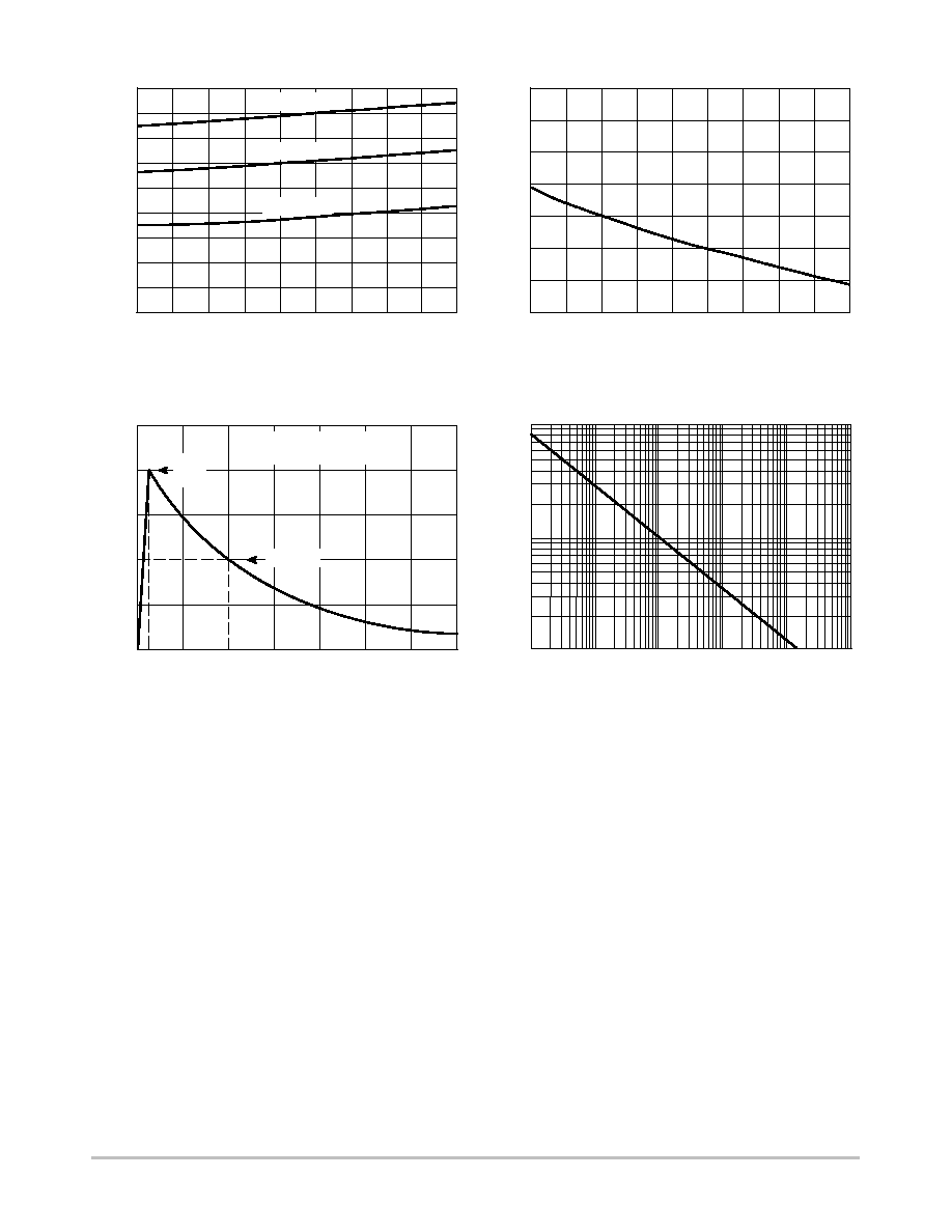
Figure 1. Off-State Current versus Temperature
TEMPERATURE (
°
C)
140
120
100
80
60
40
20
0
100
10
1
0.1
0.01
I D1
, OFF-ST
A
TE CURRENT
(
A)
Figure 2. Typical Breakdown Voltage versus
Temperature
TEMPERATURE (
°
C)
V
BR
, BREAKDOWN VOL
T
AGE (VOL
TS)
V
D1
= 50V
50
20
0
-
2
0
70
320
300
280
260
240
220
200
180
160
340
MMT05A230T3
MMT05A260T3
MMT05A310T3
µ
30
-10
10
40
60
MMT05A230T3, MMT05A260T3, MMT05A310T3
http://onsemi.com
4
Figure 3. Typical Breakover Voltage versus
Temperature
Figure 4. Typical Holding Current versus
Temperature
TEMPERATURE (
°
C)
60
20
0
-
2
0
70
100
200
300
400
500
600
700
800
I H
, HOLDING CURRENT
(mA)
V
BO
, BREAKOVER VOL
T
AGE (VOL
TS)
TEMPERATURE (
°
C)
50
30
0
-
2
0
70
320
300
280
260
240
220
200
180
160
340
MMT05A230T3
MMT05A260T3
MMT05A310T3
TIME (sec)
100
10
0.1
0.01
0.001
100
10
1
CURRENT
(A)
1
Figure 5. Exponential Decay Pulse Waveform
TIME (ms)
0
50
0
Ipp - PEAK PULSE CURRENT
- %Ipp
100
t
r
= rise time to peak value
t
f
= decay time to half value
t
r
t
f
Peak
Value
Half Value
Figure 6. Peak Surge On-State Current versus
Surge Current Duration, Sinusoidal Waveform
30
10
-10
-
10
40
20
10
60
40
50

MMT05A230T3, MMT05A260T3, MMT05A310T3
http://onsemi.com
5
TELECOM
EQUIPMENT
OUTSIDE
PLANT
TIP
RING
GND
TELECOM
EQUIPMENT
OUTSIDE
PLANT
TIP
RING
GND
TELECOM
EQUIPMENT
OUTSIDE
PLANT
TIP
RING
GND
PPTC*
PPTC*
HEAT COIL
HEAT COIL
*Polymeric PTC (positive temperature coefficient) overcurrent protection device