
ę
Semiconductor Components Industries, LLC, 2001
December, 2000 ş Rev. 3
1
Publication Order Number:
CS3524A/D
CS3524A
Voltage Mode
PWM Control Circuit with
200 mA Output Drivers
The CS3524A PWM control circuit retains the same versatile
architecture of the industry standard CS3524 (SG3524) while adding
substantial improvements.
The CS3524 is pinşcompatible with "nonşA" versions, and in most
applications can be directly interchanged. The CS3524A, however,
eliminates many of the design restrictions which had previously
required additional external circuitry.
The CS3524A includes a precision 5.0 V reference trimmed to
▒
1%
accuracy (eliminating the need for potentiometer adjustments), an
error amplifier with an output voltage swing extending to 5.0 V, and a
current sense amplifier useful in either the ground or power supply
output lines. The uncommitted 60 V, 200 mA NPN output pair greatly
enhances the output drive capability.
The CS3524A features an undervoltage lockout circuit which
disables all internal circuitry (except the reference) until the input
voltage has risen to 8.0 V. This holds standby current low until
turnşon, and greatly simplifies the design of low power, offşline
supplies. The turnşon circuit has approximately 600 mV of hysteresis
for jitter free activation.
Other improvements include a PWM latch that insures freedom
from multiple pulsing within a period, even in noisy environments;
logic to eliminate double pulsing on a single output, a 200 ns external
shutdown capability, and automatic thermal protection from excessive
chip temperature. The oscillator circuit is usable to 500 kHz and is
easier to synchronize with an external clock pulse.
Features
Ě
Precision Reference Internally Trimmed to
▒
1%
Ě
Current Limit
Ě
Undervoltage Lockout
Ě
StartşUp Supply Current < 4.0 mA
Ě
Output to 200 mA
Ě
60 V Output Capability
Ě
Wide CommonşMode Input Range for Error and Current Limit
Amplifiers
Ě
PWM Latch Insures Single Pulse per Period
Ě
Double Pulse Suppression
Ě
200 ns Shutdown
Ě
Guaranteed Frequency
Ě
Thermal Shutdown
http://onsemi.com
A
= Assembly Location
WL, L
= Wafer Lot
YY, Y
= Year
WW, W
= Work Week
SOş16L
DW SUFFIX
CASE 751G
1
16
Device
Package
Shipping
ORDERING INFORMATION
CS3524AGN16
DIPş16
25 Units/Rail
CS3524AGDW16
SOş16L
46 Units/Rail
CS3524AGDWR16
SOş16L 1000 Tape & Reel
DIPş16
N SUFFIX
CASE 648
1
16
MARKING
DIAGRAMS
16
1
CS3524A
AWLYYWW
PIN CONNECTIONS
V
OUTB
I
SENSE+
E
B
SYNC
V
IN
EA+
V
REF
EAş
1
COMP
GND
SHUTDOWN
C
T
E
A
R
T
V
OUTA
I
SENSEş
1
CS3524A
AWLYYWW
16

CS3524A
http://onsemi.com
2
Figure 1. Block Diagram
V
REF
V
OUTA
E
A
V
OUTB
E
B
SHUTDOWN
GND
V
IN
SYNC
R
T
C
T
COMP
EAş
EA+
I
SENSE+
I
SENSEş
OSC
5 V Reference
Regulator
UV
Sense
RAMP
CLOCK
COMP
+
ş
ş
+
EA
CL
PWM
Latch
Flip
Flop
Power to
Internal
Circuitry
T
R
S
S
V
IN
V
IN
200 mV
1 k
10 k
ABSOLUTE MAXIMUM RATINGS*
Rating
Value
Unit
Supply Voltage (V
IN
)
40
V
Collector Supply Voltage (V
CC
)
60
V
Output Current (Each Output)
200
mA
Reference Output Current
50
mA
Oscillator Charging Current
5.0
mA
Power Dissipation at T
A
= 25
░
C
1000
mW
Power Dissipation at T
J
= +25
░
C
Derate for Case Temperature above +25
░
C
2000
16
mW
mW/
░
C
Storage Temperature Range
ş65 to +150
░
C
Lead Temperature Soldering
Wave Solder (through hole styles only) Note 1.
Reflow (SMD styles only) Note 2.
260 peak
230 peak
░
C
░
C
1. 10 seconds max.
2. 60 seconds max above 183
░
C
*The maximum package power dissipation must be observed.

CS3524A
http://onsemi.com
3
ELECTRICAL CHARACTERISTICS
(0
░
C
T
A
+70
░
C, V
IN
= V
CC
= 20 V; unless otherwise specified.)
Characteristic
Test Conditions
Min
Typ
Max
Unit
TurnşOn Characteristics
Input Voltage
Operating Range after TurnşOn
8.0
ş
40
V
TurnşOn Threshold
ş
5.5
7.5
8.5
V
TurnşOn Current
V
IN
TurnşOn ş 100 mV
ş
2.5
4.0
mA
Operating Current
V
IN
= 8.0 to 40 V
ş
5.0
10
mA
TurnşOn Hysteresis (Note 3.)
ş
ş
0.6
ş
V
Reference Section
Output Voltage
T
A
= 25
░
C
4.9
5.0
5.2
V
Line Regulation
V
IN
= 10 to 40 V
ş
10
30
mV
Load Regulation
I
L
= 0 to 20 mA
ş
20
50
mA
Temperature Stability (Note 3.)
Over Operating Range
ş
20
50
mV
Short Circuit Current
V
REF
= 0, T
A
= 25
░
C
ş
80
100
mA
Output Noise Voltage (Note 3.)
10 Hz
f
10 kHz, T
A
= 25
░
C
ş
40
ş
Á
V
RMS
Long Term Stability (Note 3.)
T
A
= 125
░
C, 1000 Hrs.
ş
20
50
mV
Oscillator Section
R
T
= 2700
W
, C
T
= 0.01
m
F; unless otherwise specified
Initial Accuracy
T
A
= 25
░
C
39
43
47
kHz
Temperature Stability (Note 3.)
Over Operating Temperature Range
ş
1.0
2.0
%
Minimum Frequency
R
T
= 150 k
, C
T
= 0.1
Á
F
ş
ş
120
Hz
Maximum Frequency
R
T
= 2.0 k
, C
T
= 470 pF
500
ş
ş
kHz
Output Amplitude (Note 3.)
T
A
= 25
░
C
ş
3.5
ş
V
Output Pulse Width (Note 3.)
T
A
= 25
░
C
ş
0.5
ş
Á
s
Ramp Peak
ş
3.3
3.5
3.7
V
Ramp Valley
ş
0.7
0.9
1.0
V
Error Amplifier Section
V
CM
= 2.5 V; unless otherwise specified
Input Offset Voltage
ş
ş
2.0
10
mV
Input Bias Current
ş
ş
1.0
10
Á
A
Input Offset Current
ş
ş
0.5
1.0
Á
A
Common Mode Rejection Ratio
V
CM
= 1.5 to 5.5 V
60
75
ş
dB
Power Supply Rejection Ratio
V
IN
= 10 to 40 V
50
60
ş
dB
Output Swing
Minimum Total Range
0.5
ş
5.0
V
Open Loop Voltage Gain
V
OUT
= 1.0 to 4.0 V, R
L
10 M
60
80
ş
dB
GainşBandwidth (Note 3.)
T
A
= 25
░
C, A
V
= 0 dB
ş
3.0
ş
MHz
Current Limit Amplifier
V
SENSE
= V
O
; unless otherwise specified
Input Offset Voltage
T
A
= 25
░
C, EA Set for Max. Output
180
200
220
mV
Input Offset Voltage
Over Operating Temperature Range
170
ş
230
mV
Input Bias Current
ş
ş
ş1.0
ş10
Á
A
Common Mode Rejection Ratio
V
SENSE
= 0 to 15 V
50
60
ş
dB
Power Supply Rejection Ratio
V
IN
= 10 to 40 V
50
60
ş
dB
3. These parameters are guaranteed by design but not 100% tested in production.
CS3524A
http://onsemi.com
4
ELECTRICAL CHARACTERISTICS (continued)
(0
░
C
T
A
+70
░
C, V
IN
= V
CC
= 20 V; unless otherwise specified.)
Characteristic
Unit
Max
Typ
Min
Test Conditions
Current Limit Amplifier (continued)
V
SENSE
= V
O
; unless otherwise specified
Output Swing
Minimum Total Range
0.5
ş
5.0
V
Open Loop Voltage Gain
V
OUT
= 1.0 to 4.0 V, R
L
10 M
70
80
ş
dB
Delay Time (Note 4.)
V
IN
= 300 mV
ş
300
ş
ns
Output Section (Each Output)
Collector Emitter Voltage
I
C
= 100
Á
A
60
80
ş
V
Collector Leakage Current
V
CE
= 50 V
ş
0.1
20
Á
A
Saturation
I
C
= 20 mA
I
C
= 200 mA
ş
ş
0.2
1.0
0.4
2.2
V
V
Emitter Output Voltage
I
E
= 50 mA
17
18
ş
V
Rise Time (Note 4.)
T
A
= 25
░
C, R = 2.0 k
ş
200
ş
ns
Fall Time (Note 4.)
T
A
= 25
░
C, R = 2.0 k
ş
100
ş
ns
Comparator Delay (Note 4.)
T
A
= 25
░
C, V
COMP
to V
OUT
ş
300
ş
ns
Shutdown Delay (Note 4.)
T
A
= 25
░
C, V
SHUT
to V
OUT
ş
200
ş
ns
Shutdown Threshold
T
A
= 25
░
C, R
C
= 2.0 k
0.5
0.7
1.0
V
Thermal Shutdown (Note 4.)
ş
ş
165
ş
░
C
4. These parameters are guaranteed by design but not 100% tested in production.
TYPICAL PERFORMANCE CHARACTERISTICS
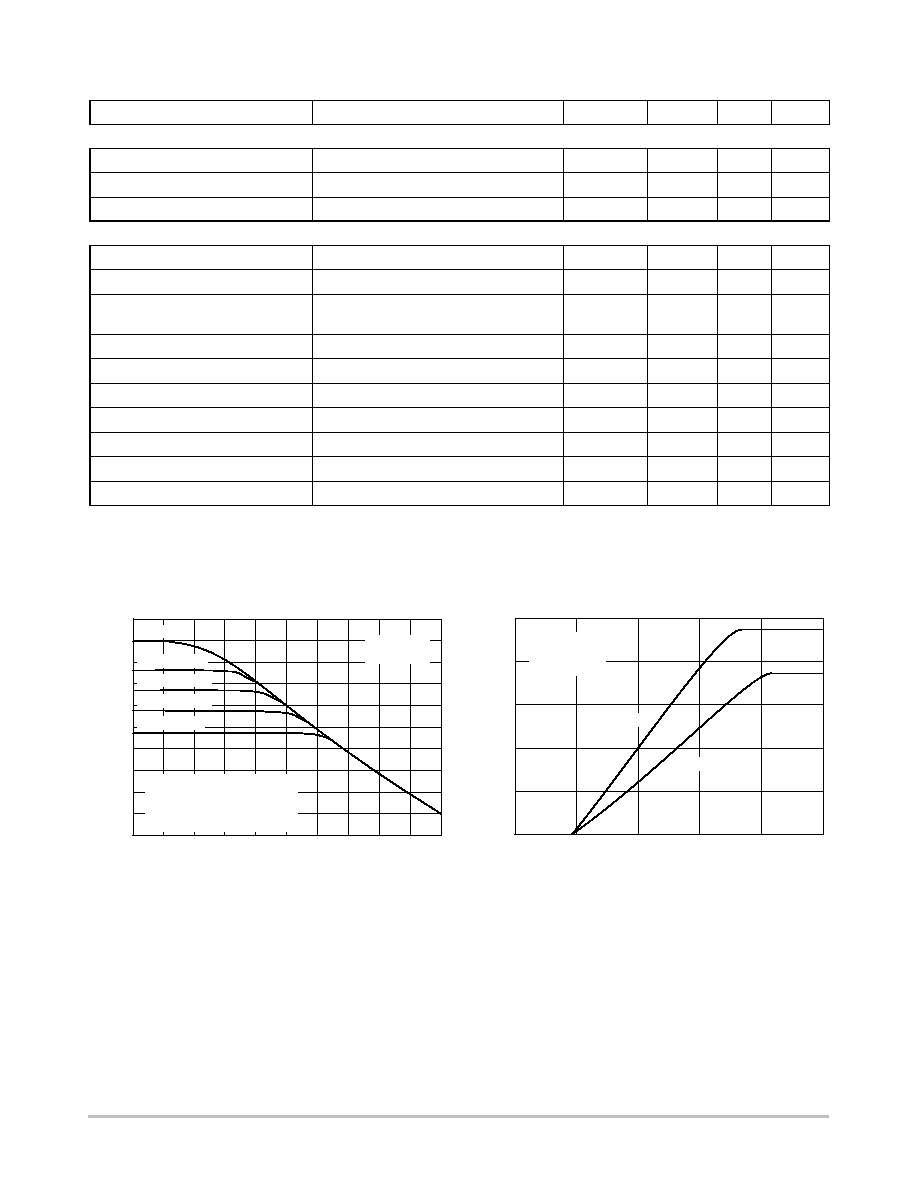
Figure 2. Error Amplifier Voltage Gain vs.
Frequency Over RF
Figure 3. Duty Cycle vs. Input Voltage
100
1 k
10 k
100 k
1 M
Frequency (Hz)
80
60
40
20
0
Open V
oltage Gain (dB)
R
F
=
R
F
= 1 M
R
F
= 300 k
R
F
= 100 k
R
F
= 30 k
V
IN
= 20 V
T
A
= 25
░
C
R
F
is impedance to ground.
Values below 30 k
will
begin to limit the maximum
dutyşcycle.
0
1
2
3
5
Input Voltage V
IN
50
40
30
0
DutyşCycle (One
Output)
ş %
10
20
4
V
IN
= 20 V
R
T
= 2700
T
A
= 25
░
C
C
T
= 10
Á
F
C
T
= 1
Á
F
CS3524A
http://onsemi.com
5
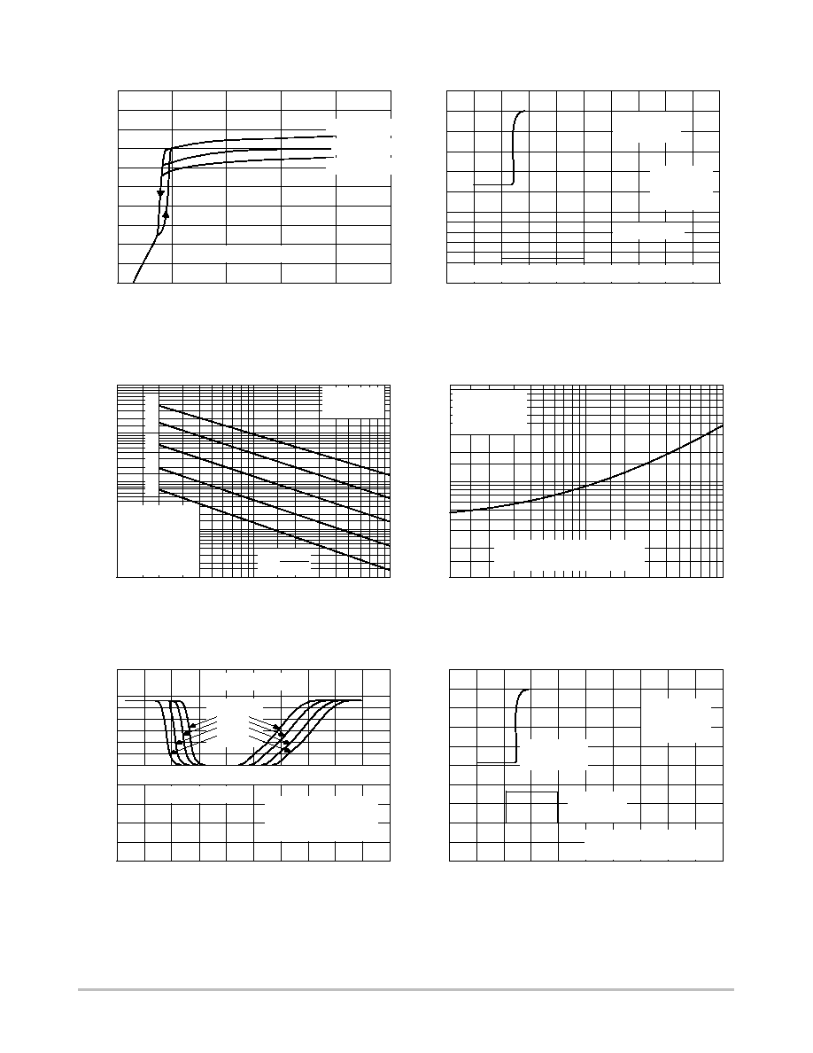
Figure 4. Quiescent Supply Current vs. Supply
Voltage Over Temperature
Figure 5. Shutdown Delay from PWM Comparator
10
20
30
40
50
Supply Voltage V
IN
(V)
9
7
5
3
1
Quiescent Current (mA)
10
8
6
4
2
0
0
T
A
= ş55
░
C
T
A
= 25
░
C
T
A
= 125
░
C
Note: Outputs off. R
T
=
0
1
2
3
Delay Time (
Á
s)
20
Input (V)
15
10
5
0
5
4
3
2
1
0
Output (V)
V
IN
= 20 V
R
L
= 2 k
T
A
= 25
░
C
Note: Minimum input pulse width to latch is 200 ns.
Output at
V
OA
or V
OB
Input at V
OB
Figure 6. Oscillator Frequency vs. Timing
Components Resistor Over Timing Capacitance
1 M
100 k
10 k
100
Oscillator Frequency (Hz)
1 k
1
2
5
20
100
Timing Resistor, R
T
(k
)
50
10
V
IN
= 20 V
T
A
= 25
░
C
f
[
1.15
RTCT
1. C
T
= 1.0 nF
2. C
T
= 3.0 nF
3. C
T
= 10 nF
4. C
T
= 30 nF
5. C
T
= 100 nF
1
2
3
4
5
1
2
5
20
100
Timing Capacitor, C
T
(nF)
50
10
10
5.0
0.1
Output Dead T
ime (
Á
s)
2.0
1.0
0.5
0.2
V
IN
= 20 V
R
T
= 2700
T
A
= 25
░
C
Note: Dead time = osc output
pulse width plus output delay
Figure 7. Output Dead Time vs. Timing Capacitor
Value
1
2
4
Delay Time (
Á
s)
Input (V)
Output (V)
5
6
4
3
2
1
0
0.2
0.1
0
3
0
Output at COMP
Overdrive
5%
10%
20%
50%
Input at I
SENSE+
V
IN
= 20 V, T
A
= 25
░
C
EA+ = V
REF
I
SENSEş
= GND
0
1
2
3
Delay Time (
Á
s)
Note: Minimum input pulse
width to latch is 200 ns.
Input (V)
Output (V)
5
10
0
1.0
0.5
0
15
20
V
IN
= 20 V
R
L
= 2.0 k
T
A
= 25
░
C
Output at
V
OA
or V
OB
Input at
Shutdown
Figure 8. Current Limit Amplifier Delay
Figure 9. TurnşOff Delay from Shutdown
CS3524A
http://onsemi.com
6
0
50
100
150
Output Collector Current (mA)
V
CE
Sat (V)
5
3
2
1
0
4
200
250
T
A
= 125
░
C
T
A
= 25
░
C
T
A
= ş55
░
C
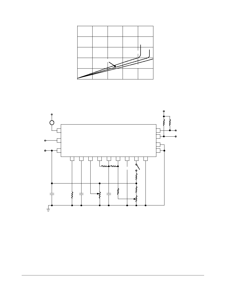
Figure 10. Output Saturation Voltage vs. Output
Current Over Temperature
Figure 11. Open Loop Test Circuit
V
REF
V
OUTA
E
A
V
OUTB
E
B
SHUTDOWN
GND
V
IN
SYNC
R
T
C
T
COMP
EAş
EA+
I
SENSE+
I
SENSEş
CS3524A
V
CC
2 k
1 W
2 k
1 W
2 k
SHUTDOWN
R
T
C
T
0.1
I
S
100 k
100 k
10 k
1 k
2 k
0.1
10 k
Note: The CS3524A should be able to be tested in any
3524 test circuit with two possible exceptions:
1. The higher gainşbandwidth of the current limit
amplifier in the CS3524A may cause oscillations in
an uncompensated 3524 test circuit.
2. The effect of the shutdown cannot be seen at the
compensation terminal, but must be observed at the
outputs.

CS3524A
http://onsemi.com
7
PACKAGE DIMENSIONS
DIPş16
N SUFFIX
CASE 648ş08
ISSUE R
NOTES:
1. DIMENSIONING AND TOLERANCING PER ANSI
Y14.5M, 1982.
2. CONTROLLING DIMENSION: INCH.
3. DIMENSION L TO CENTER OF LEADS WHEN
FORMED PARALLEL.
4. DIMENSION B DOES NOT INCLUDE MOLD FLASH.
5. ROUNDED CORNERS OPTIONAL.
şAş
B
F
C
S
H
G
D
J
L
M
16 PL
SEATING
1
8
9
16
K
PLANE
şTş
M
A
M
0.25 (0.010)
T
DIM
MIN
MAX
MIN
MAX
MILLIMETERS
INCHES
A
0.740
0.770
18.80
19.55
B
0.250
0.270
6.35
6.85
C
0.145
0.175
3.69
4.44
D
0.015
0.021
0.39
0.53
F
0.040
0.70
1.02
1.77
G
0.100 BSC
2.54 BSC
H
0.050 BSC
1.27 BSC
J
0.008
0.015
0.21
0.38
K
0.110
0.130
2.80
3.30
L
0.295
0.305
7.50
7.74
M
0
10
0
10
S
0.020
0.040
0.51
1.01
_
_
_
_
SOş16L
DW SUFFIX
CASE 751Gş03
ISSUE B
D
14X
B
16X
SEATING
PLANE
S
A
M
0.25
B
S
T
16
9
8
1
h
X 45
_
M
B
M
0.25
H
8X
E
B
A
e
T
A1
A
L
C
q
NOTES:
1. DIMENSIONS ARE IN MILLIMETERS.
2. INTERPRET DIMENSIONS AND TOLERANCES
PER ASME Y14.5M, 1994.
3. DIMENSIONS D AND E DO NOT INLCUDE MOLD
PROTRUSION.
4. MAXIMUM MOLD PROTRUSION 0.15 PER SIDE.
5. DIMENSION B DOES NOT INCLUDE DAMBAR
PROTRUSION. ALLOWABLE DAMBAR
PROTRUSION SHALL BE 0.13 TOTAL IN EXCESS
OF THE B DIMENSION AT MAXIMUM MATERIAL
CONDITION.
DIM
MIN
MAX
MILLIMETERS
A
2.35
2.65
A1
0.10
0.25
B
0.35
0.49
C
0.23
0.32
D
10.15
10.45
E
7.40
7.60
e
1.27 BSC
H
10.05
10.55
h
0.25
0.75
L
0.50
0.90
q
0
7
_
_
PACKAGE THERMAL DATA
Parameter
DIPş16
SOş16L
Unit
R
JC
Typical
42
23
░
C/W
R
JA
Typical
80
105
░
C/W

CS3524A
http://onsemi.com
8
ON Semiconductor and are trademarks of Semiconductor Components Industries, LLC (SCILLC). SCILLC reserves the right to make changes
without further notice to any products herein. SCILLC makes no warranty, representation or guarantee regarding the suitability of its products for any particular
purpose, nor does SCILLC assume any liability arising out of the application or use of any product or circuit, and specifically disclaims any and all liability,
including without limitation special, consequential or incidental damages. "Typical" parameters which may be provided in SCILLC data sheets and/or
specifications can and do vary in different applications and actual performance may vary over time. All operating parameters, including "Typicals" must be
validated for each customer application by customer's technical experts. SCILLC does not convey any license under its patent rights nor the rights of others.
SCILLC products are not designed, intended, or authorized for use as components in systems intended for surgical implant into the body, or other applications
intended to support or sustain life, or for any other application in which the failure of the SCILLC product could create a situation where personal injury or
death may occur. Should Buyer purchase or use SCILLC products for any such unintended or unauthorized application, Buyer shall indemnify and hold
SCILLC and its officers, employees, subsidiaries, affiliates, and distributors harmless against all claims, costs, damages, and expenses, and reasonable
attorney fees arising out of, directly or indirectly, any claim of personal injury or death associated with such unintended or unauthorized use, even if such claim
alleges that SCILLC was negligent regarding the design or manufacture of the part. SCILLC is an Equal Opportunity/Affirmative Action Employer.
PUBLICATION ORDERING INFORMATION
CENTRAL/SOUTH AMERICA:
Spanish Phone: 303ş308ş7143 (MonşFri 8:00am to 5:00pm MST)
Email: ONlitşspanish@hibbertco.com
ASIA/PACIFIC: LDC for ON Semiconductor ş Asia Support
Phone: 303ş675ş2121 (TueşFri 9:00am to 1:00pm, Hong Kong Time)
Toll Free from Hong Kong & Singapore:
001ş800ş4422ş3781
Email: ONlitşasia@hibbertco.com
JAPAN: ON Semiconductor, Japan Customer Focus Center
4ş32ş1 NishişGotanda, Shinagawaşku, Tokyo, Japan 141ş0031
Phone: 81ş3ş5740ş2745
Email: r14525@onsemi.com
ON Semiconductor Website: http://onsemi.com
For additional information, please contact your local
Sales Representative.
CS3524A/D
NORTH AMERICA Literature Fulfillment:
Literature Distribution Center for ON Semiconductor
P.O. Box 5163, Denver, Colorado 80217 USA
Phone: 303ş675ş2175 or 800ş344ş3860 Toll Free USA/Canada
Fax: 303ş675ş2176 or 800ş344ş3867 Toll Free USA/Canada
Email: ONlit@hibbertco.com
Fax Response Line: 303ş675ş2167 or 800ş344ş3810 Toll Free USA/Canada
N. American Technical Support: 800ş282ş9855 Toll Free USA/Canada
EUROPE: LDC for ON Semiconductor ş European Support
German Phone: (+1) 303ş308ş7140 (MonşFri 2:30pm to 7:00pm CET)
Email: ONlitşgerman@hibbertco.com
French Phone: (+1) 303ş308ş7141 (MonşFri 2:00pm to 7:00pm CET)
Email: ONlitşfrench@hibbertco.com
English Phone: (+1) 303ş308ş7142 (MonşFri 12:00pm to 5:00pm GMT)
Email: ONlit@hibbertco.com
EUROPEAN TOLLşFREE ACCESS*: 00ş800ş4422ş3781
*Available from Germany, France, Italy, UK, Ireland