ˇ Semiconductor
MSM9888L
1/14
ˇ Semiconductor
MSM9888L
Flash-driving Recording and Playback IC
GENERAL DESCRIPTION
The MSM 9888L is a recording and playback IC that is controlled by the micro-controller in serial
mode, compresses voice with the Oki ADPCM system with high tone quality, and directly stores
voice data inthe serial voice flash momory. This IC can operate in a range of 2.7 to 3.6 V and
contains a mask ROM. Since the package is small and backup is not needed, this recording and
playback IC is suitable for the voice system such as handy terminals.
FEATURES
· Voice analyzing and synthesizing system
: 4-bit OKI ADPCM system
·
8-bit OKI non-linear PCM system
(for ROM playback only)
· Built-in 12-bit A/D
·
D/A converter
· Built-in LPF
: Attenuation rate 40 dB/oct
· Sampling frequency (for 4.096 MHz of source oscillation frequency)
: 2.0 kHz, 2.7 kHz, 3.2kHz, 4.0 kHz, 5.3 kHz, 6.4 kHz, 8 kHz
· External memory for variable message
: 1Mb, 2Mb, 4Mb, 8Mb, serial voice flash memory
· Recording time (When the 1Mb serial voice flash is used)
: Approximately 32 seconds (Fsam=8.0 kHz)
: Approximately 40 seconds (Fsam=6.4 kHz)
: Approximately 65 seconds (Fsam=4.0 kHz)
· Built-in 512Kb mask ROM for fixed message
· Playback time for fixed message
: Approximately 15 seconds (Fsam=8.0 kHz)
: Approximately 20 seconds (Fsam=6.4 kHz)
: Approximately 31 seconds (Fsam=4.0 kHz)
· Number of pharase
Variable message
: 63 phrases
Fixed message
: 255 phrases
· Any data can be written to and read from a part in the voice flash memory.
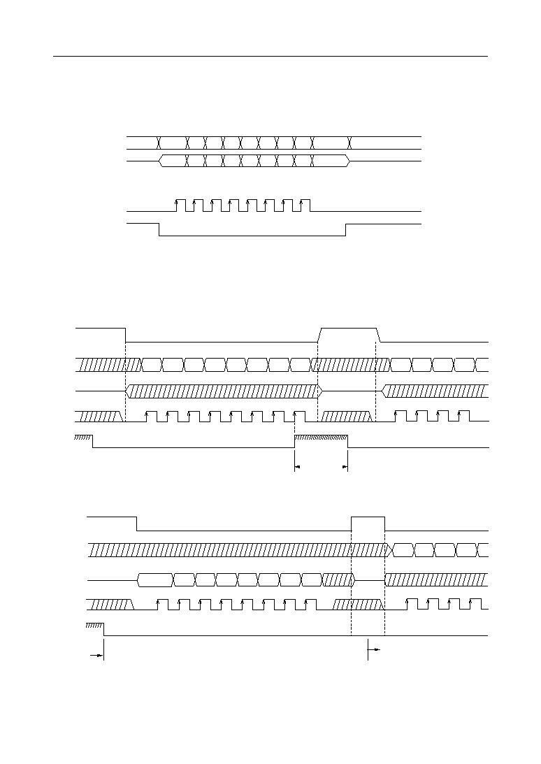
· Serial microcontroller interface
· Source oscillation frequency
: 4 MHz to 6 MHz
· Supply voltage
: 2.7 V to 3.6 V
· Operating temperature
: 10
°
C to 70
°
C
· Package :
30-pin plastic SSOP (SSOP30-P-56-0.65-K)(Product name : MSM9888LGS-AK)
E2D0083-27-44
Preliminary
This version: Jan. 1998
Previous version: May. 1997
ˇ Semiconductor
MSM9888L
3/14
PIN DESCRIPTION
Symbol
I/O
Description
Inputs the 8-bit command data.
DI
I
Pin
14
Outputs the 8-bit status data.
DO
O
13
Inputs the data transfer clock for the DI and DO pins.
SCK
I
12
Accepts the SCK pulse, when CS is "L" level. Does not accept the SCL pulse
when CS is "H" level.
CS
I
9
Indicates "H" level during command execution. When driven high, do not input a
command from the external micro-controller.
BUSY
O
20
Outputs "H" level during recording or playback.
MON
O
15
1s connected to the DI pin of the serial voice flash memory.
FDI
O
23
1s connected to the DO pin of the serial voice flash memory.
FDO
I
22
1s connected to the SCK pin of the serial voice flash memory.
FSCK
O
24
1s connected to the CS pin of the serial voice flash memory.
FCS
O
25
1s connected to the PRT pin of the serial voice flash memory.
FPRT
O
26
1s connected to the RESET pin of the serial voice flash memory.
FRESET
O
27
Oscillator connecting pins. When using an external clock, input the clock from
the XT pin and keep the XT pin open.
XT
I
10
XT
O
11
RESET
I
16
The LSI is reset and starts oscillation when "L" level is input, keep "L" level during
oscillation stabilization time. Set to "H" level after oscillation stabilizes.
Analog reference voltage (Signal Ground) output pin
SG
O
1
Built-in OP amplifier's invention input pin. The non-invention input pin is
internally connected to SG.
LIN
I
28
Built-in OP amplifier's output pin
LOUT
O
29
Built-in 12-bit AD converter's input signal
ADIN
I
4
Connected to the LOUT pin when recording mode, and to the DA converter's
output pin when playback mode. Connected to the built-in LPF's input (FIN pin).
AMON
O
2
Built-in LPF's input pin
FIN
I
3
Built-in LPF's output pin. Connected to the AD converter's input (ADIN pin).
FOUT
O
5
Built-in LPF's output pin. This is the output pin the played back waveform and
connected to the speaker driving amplifier.
AOUT
O
6
TEST0-2
I
LSI testing pins. Fix to "L".
Digital power supply pin. Insert a bypass capacitor of 0.1mF or higher between
this pin and DGND pin.
DV
DD
--
8
Digital DGND pin
DGND
--
21
Analog power supply pin. Insert a bypass capacitor of 0.1mF or higher between
this pin and AGND pin.
AV
DD
--
7
Analog GND pin
AGND
--
30
17-19