TL H 11754
LM45BLM45C
SOT-23
Precision
Centigrade
Temperature
Sensors
May 1995
LM45B LM45C
SOT-23 Precision Centigrade Temperature Sensors
General Description
The LM45 series are precision integrated-circuit tempera-
ture sensors whose output voltage is linearly proportional to
the Celsius (Centigrade) temperature The LM45 does not
require any external calibration or trimming to provide accu-
racies of
g
2 C at room temperature and
g
3 C over a full
b
20 to
a
100 C temperature range Low cost is assured by
trimming and calibration at the wafer level The LM45's low
output impedance linear output and precise inherent cali-
bration make interfacing to readout or control circuitry espe-
cially easy It can be used with a single power supply or with
plus and minus supplies As it draws only 120 mA from its
supply it has very low self-heating less than 0 2 C in still
air The LM45 is rated to operate over a
b
20 to
a
100 C
temperature range
Applications
Y
Battery Management
Y
FAX Machines
Y
Printers
Y
Portable Medical Instruments
Y
HVAC
Y
Power Supply Modules
Y
Disk Drives
Y
Computers
Y
Automotive
Features
Y
Calibrated directly in
Celsius (Centigrade)
Y
Linear
a
10 0 mV C scale factor
Y
g
3 C accuracy guaranteed
Y
Rated for full
b
20 to
a
100 C range
Y
Suitable for remote applications
Y
Low cost due to wafer-level trimming
Y
Operates from 4 0V to 10V
Y
Less than 120 mA current drain
Y
Low self-heating 0 20 C in still air
Y
Nonlinearity only
g
0 8 C max over temp
Y
Low impedance output 20X for 1 mA load
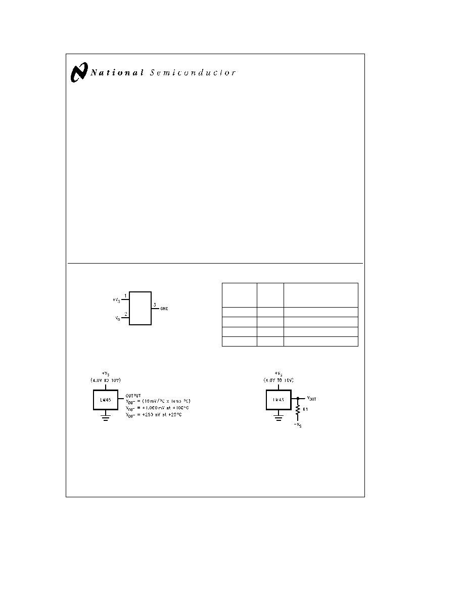
Connection Diagram
SOT-23
TL H 11754 ş 1
Top View
See NS Package Number M03B
(JEDEC Registration TO-236AB)
SOT-23
Order
Device
Number
Marking
Supplied As
LM45BIM3
T4B
250 Units on Tape and Reel
LM45BIM3X
T4B
3000 Units on Tape and Reel
LM45CIM3
T4C
250 Units on Tape and Reel
LM45CIM3X
T4C
3000 Units on Tape and Reel
Typical Applications
TL H 11754 ş 3
FIGURE 1 Basic Centigrade Temperature
Sensor (
a
2 5 C to
a
100 C)
TL H 11754 ş 4
Choose R
1
e b
V
S
50 mA
V
OUT
e
(10 mV C
c
Temp C)
V
OUT
e a
1 000 mV at
a
100 C
e a
250 mV at
a
25 C
e b
200 mV at
b
20 C
FIGURE 2 Full-Range Centigrade
Temperature Sensor (
b
20 C to
a
100 C)
C1995 National Semiconductor Corporation
RRD-B30M75 Printed in U S A

Absolute Maximum Ratings
(Note 1)
Supply Voltage
a
12V to
b
0 2V
Output Voltage
a
V
S
a
0 6V to
b
1 0V
Output Current
10 mA
Storage Temperature
b
65 C to
a
150 C
Lead Temperature
SOT Package (Note 2)
Vapor Phase (60 seconds)
215 C
Infrared (15 seconds)
220 C
ESD Susceptibility (Note 3)
Human Body Model
2000V
Machine Model
TBD
Operating Ratings
(Note 1)
Specified Temperature Range
(Note 4)
T
MIN
to T
MAX
LM45B LM45C
b
20 C to
a
100 C
Operating Temperature Range
LM45B LM45C
b
40 C to
a
125 C
Supply Voltage Range (
a
V
S
)
a
4 0V to
a
10V
Electrical Characteristics
Unless otherwise noted these specifications apply for
a
V
S
e a
5Vdc and I
LOAD
e
a
50 mA in the circuit of
Figure 2 These specifications also apply from
a
2 5 C to T
MAX
in the circuit of
Figure 1 for
a
V
S
e
a
5Vdc Boldface limits apply for T
A
e
T
J
e
T
MIN
to T
MAX
all other limits T
A
e
T
J
e a
25 C unless otherwise noted
Parameter
Conditions
LM45B
LM45C
(Limit)
Units
Typical
Limit
Typical
Limit
(Note 5)
(Note 5)
Accuracy
T
A
e a
25 C
g
2 0
g
3 0
C (max)
(Note 6)
T
A
e
T
MAX
g
3 0
g
4 0
C (max)
T
A
e
T
MIN
g
3 0
g
4 0
C (max)
Nonlinearity
T
MIN
s
T
A
s
T
MAX
g
0 8
g
0 8
C (max)
(Note 7)
Sensor Gain
T
MIN
s
T
A
s
T
MAX
a
9 7
a
9 7
mV C (min)
(Average Slope)
a
10 3
a
10 3
mV C (max)
Load Regulation (Note 8)
0
s
I
L
s
a
1 mA
g
35
g
35
mV mA (max)
Line Regulation
a
4 0V
s
a
V
S
s
a
10V
g
0 80
g
0 80
mV V (max)
(Note 8)
g
1 2
g
1 2
mV V (max)
Quiescent Current
a
4 0V
s
a
V
S
s
a
10V
a
25 C
120
120
m
A (max)
(Note 9)
a
4 0V
s
a
V
S
s
a
10V
160
160
m
A (max)
Change of Quiescent
4 0V
s
a
V
S
s
10V
2 0
2 0
m
A (max)
Current (Note 8)
Temperature Coefficient
a
2 0
a
2 0
m
A C
of Quiescent Current
Minimum Temperature
In circuit of
a
2 5
a
2 5
C (min)
for Rated Accuracy
Figure 1 I
L
e
0
Long Term Stability (Note 10)
T
J
e
T
MAX
for 1000 hours
g
0 12
g
0 12
C
Note 1
Absolute Maximum Ratings indicate limits beyond which damage to the device may occur DC and AC electrical specifications do not apply when operating
the device beyond its rated operating conditions
Note 2
See AN-450 ``Surface Mounting Methods and Their Effect on Product Reliability'' or the section titled ``Surface Mount'' found in a current National
Semiconductor Linear Data Book for other methods of soldering surface mount devices
Note 3
Human body model 100 pF discharged through a 1 5 kX resistor Machine model 200 pF discharged directly into each pin
Note 4
Thermal resistance of the SOT-23 package is 260 C W junction to ambient when attached to a printed circuit board with 2 oz foil as shown in
Figure 3
Note 5
Limits are guaranteed to National's AOQL (Average Outgoing Quality Level)
Note 6
Accuracy is defined as the error between the output voltage and 10 mv C times the device's case temperature at specified conditions of voltage current
and temperature (expressed in C)
Note 7
Nonlinearity is defined as the deviation of the output-voltage-versus-temperature curve from the best-fit straight line over the device's rated temperature
range
Note 8
Regulation is measured at constant junction temperature using pulse testing with a low duty cycle Changes in output due to heating effects can be
computed by multiplying the internal dissipation by the thermal resistance
Note 9
Quiescent current is measured using the circuit of
Figure 1
Note 10
For best long-term stability any precision circuit will give best results if the unit is aged at a warm temperature and or temperature cycled for at least 46
hours before long-term life test begins This is especially true when a small (Surface-Mount) part is wave-soldered allow time for stress relaxation to occur
2
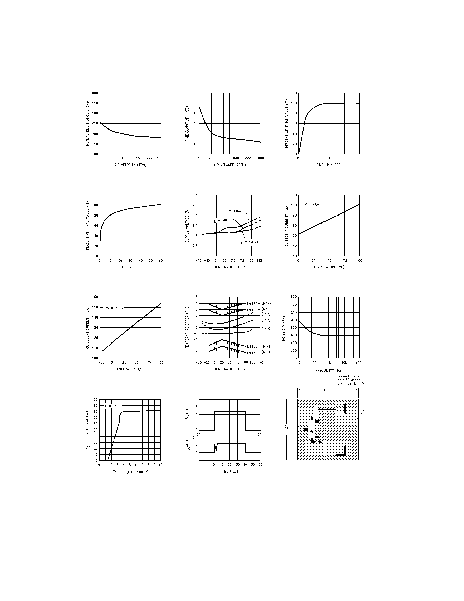
Typical Performance Characteristics
To generate these curves the LM45 was mounted to a printed circuit board as shown in
Figure 3
Junction to Air
Thermal Resistance
Thermal Time Constant
with Heat Sink (
Figure 3 )
Thermal Response in Still Air
with Heat Sink
in Stirred Oil Bath
Thermal Response
vs Temperature
Start-Up Voltage
(In Circuit of
Figure 1 )
vs Temperature
Quiescent Current
(In Circuit of
Figure 2 )
vs Temperature
Quiescent Current
(Guaranteed)
Accuracy vs Temperature
Noise Voltage
vs Supply Current
Supply Voltage
Start-Up Response
TL H 11754 ş 23
FIGURE 3 Printed Circuit Board Used
for Heat Sink to Generate All Curves
Square Printed Circuit Board
with 2 oz Foil or Similar
TL H 11754 ş 5
3
Applications
The LM45 can be applied easily in the same way as other
integrated-circuit temperature sensors It can be glued or
cemented to a surface and its temperature will be within
about 0 2 C of the surface temperature
This presumes that the ambient air temperature is almost
the same as the surface temperature if the air temperature
were much higher or lower than the surface temperature
the actual temperature of the LM45 die would be at an inter-
mediate temperature between the surface temperature and
the air temperature
To ensure good thermal conductivity the backside of the
LM45 die is directly attached to the GND pin The lands and
traces to the LM45 will of course be part of the printed
circuit board which is the object whose temperature is be-
ing measured These printed circuit board lands and traces
will not cause the LM45s temperature to deviate from the
desired temperature
Alternatively the LM45 can be mounted inside a sealed-end
metal tube and can then be dipped into a bath or screwed
into a threaded hole in a tank As with any IC the LM45 and
accompanying wiring and circuits must be kept insulated
and dry to avoid leakage and corrosion This is especially
true if the circuit may operate at cold temperatures where
condensation can occur Printed-circuit coatings and var-
nishes such as Humiseal and epoxy paints or dips are often
used to insure that moisture cannot corrode the LM45 or its
connections
Temperature Rise of LM45 Due to Self-Heating
(Thermal Resistance)
SOT-23
SOT-23
no heat sink
small heat fin
Still air
450 C W
260 C W
Moving air
180 C W
Heat sink used is
square printed circuit board with 2 oz foil with part
attached as shown in
Figure 3
Part soldered to 30 gauge wire
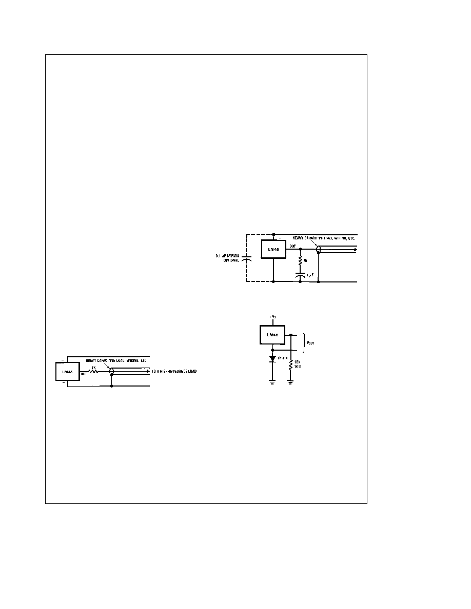
Typical Applications
CAPACITIVE LOADS
Like most micropower circuits the LM45 has a limited ability
to drive heavy capacitive loads The LM45 by itself is able to
drive 500 pF without special precautions If heavier loads
are anticipated it is easy to isolate or decouple the load with
a resistor see
Figure 4 Or you can improve the tolerance of
capacitance with a series R-C damper from output to
ground see
Figure 5
Any linear circuit connected to wires in a hostile environ-
ment can have its performance affected adversely by in-
tense electromagnetic sources such as relays radio trans-
mitters motors with arcing brushes SCR transients etc as
its wiring can act as a receiving antenna and its internal
junctions can act as rectifiers For best results in such cas-
es a bypass capacitor from V
IN
to ground and a series R-C
damper such as 75X in series with 0 2 or 1 mF from output
to ground as shown in
Figure 5 are often useful
TL H 11754 ş 8
FIGURE 4 LM45 with Decoupling from Capacitive Load
TL H 11754 ş 9
FIGURE 5 LM45 with R-C Damper
TL H 11754 ş 12
FIGURE 6 Temperature Sensor
Single Supply
b
20 C to
a
100 C
4
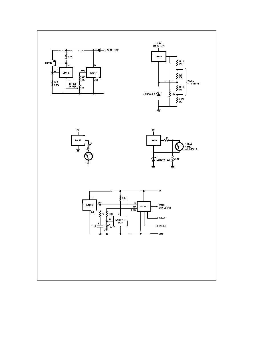
Typical Applications
(Continued)
TL H 11754 ş 14
FIGURE 7 4-to-20 mA Current Source (0 C to
a
100 C)
TL H 11754 ş 15
FIGURE 8 Fahrenheit Thermometer
TL H 11754 ş 16
FIGURE 9 Centigrade Thermometer (Analog Meter)
TL H 11754 ş 17
FIGURE 10 Expanded Scale Thermometer
(50 to 80 Fahrenheit for Example Shown)
TL H 11754 ş 18
FIGURE 11 Temperature To Digital Converter (Serial Output) (
a
128 C Full Scale)
5