LM4041
Precision Micropower Shunt Voltage Reference
General Description
Ideal for space critical applications, the LM4041 precision
voltage reference is available in the sub-miniature SC70 and
SOT-23 surface-mount packages. The LM4041's advanced
design eliminates the need for an external stabilizing capaci-
tor while ensuring stability with any capacitive load, thus
making the LM4041 easy to use. Further reducing design
effort is the availability of a fixed (1.225V) and adjustable
reverse breakdown voltage. The minimum operating current
is 60 µA for the LM4041-1.2 and the LM4041-ADJ. Both
versions have a maximum operating current of 12 mA.
The LM4041 utilizes fuse and zener-zap reverse breakdown
or reference voltage trim during wafer sort to ensure that the
prime parts have an accuracy of better than
±
0.1%
(A grade) at 25°C. Bandgap reference temperature drift cur-
vature correction and low dynamic impedance ensure stable
reverse breakdown voltage accuracy over a wide range of
operating temperatures and currents.
Features
n
Small packages: SOT-23, TO-92, and SC70
n
No output capacitor required
n
Tolerates capacitive loads
n
Reverse breakdown voltage options of 1.225V and
adjustable
Key Specifications (LM4041-1.2)
j
Output voltage tolerance
(A grade, 25°C)
±
0.1%(max)
j
Low output noise
(10 Hz to 10kHz)
20µV
rms
j
Wide operating current range
60µA to 12mA
j
Industrial temperature range
-40°C to +85°C
j
Extended temperature range
-40°C to +125°C
j
Low temperature coefficient
100 ppm/°C (max)
Applications
n
Portable, Battery-Powered Equipment
n
Data Acquisition Systems
n
Instrumentation
n
Process Control
n
Energy Management
n
Automotive
n
Precision Audio Components
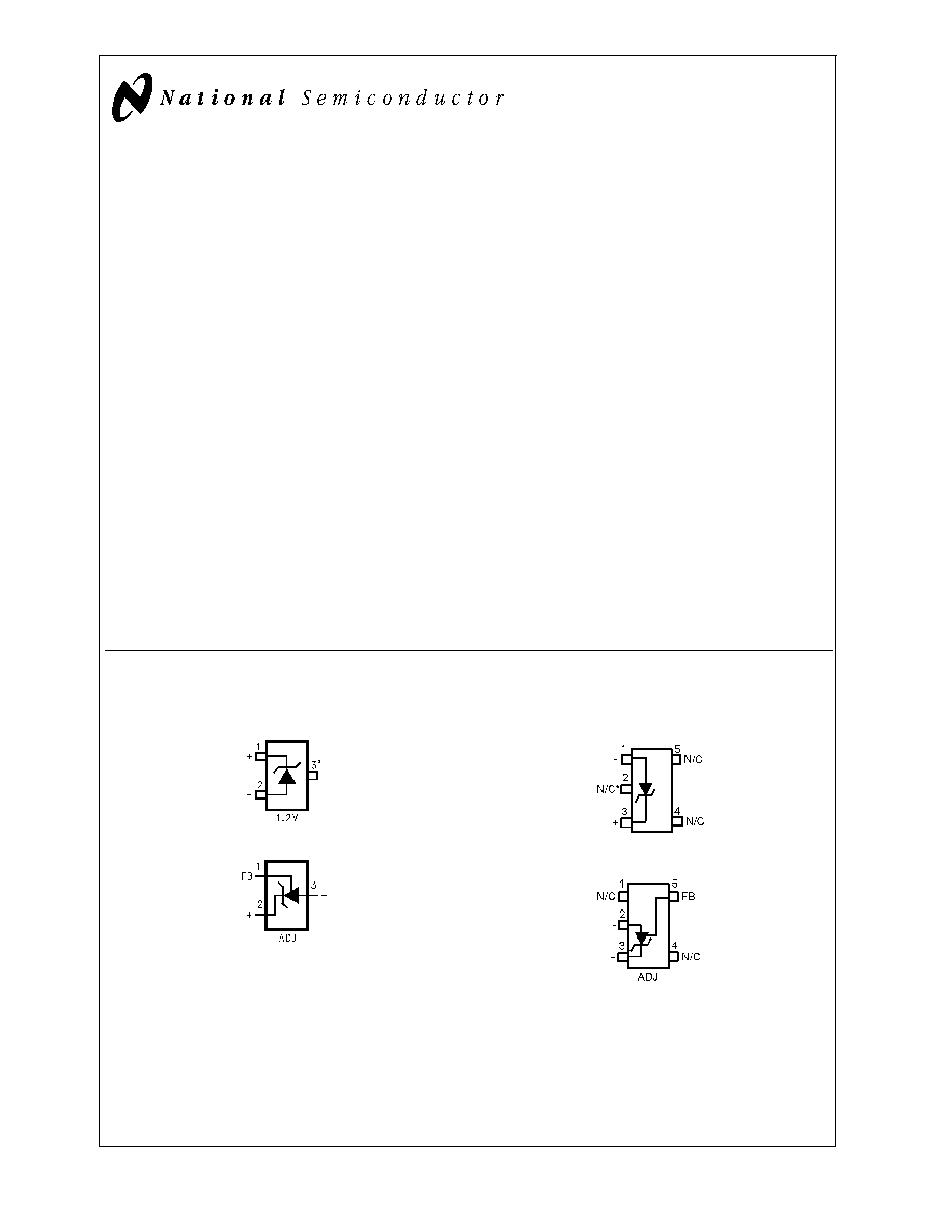
Connection Diagrams
SOT-23
DS011392-1
*This pin must be left floating or connected to pin 2.
DS011392-40
Top View
See NS Package Number MF03A
(JEDEC Registration TO-236AB)
SC-70
DS011392-46
*This pin must be left floating or connected to pin 1.
DS011392-47
Top View
See NS Package Number MAA05A
January 2001
LM4041
Precision
Micropower
Shunt
V
oltage
Reference
© 2001 National Semiconductor Corporation
DS011392
www.national.com

Connection Diagrams
(Continued)
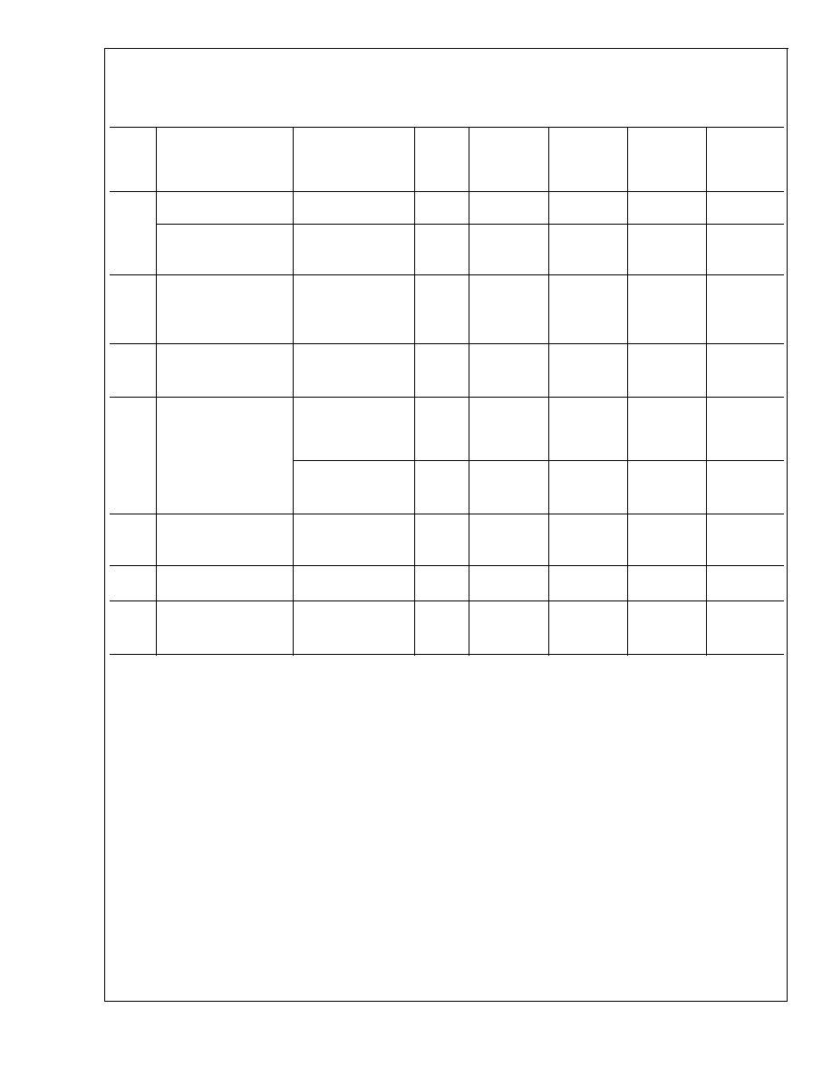
Ordering Information
Reverse
Breakdown
Voltage Tolerance
at 25°C and
Average Reverse
Breakdown
Voltage
Temperature
Coefficient
Package
NS
Package
Number
M3 (SOT-23)
M7 (SC70)
Z (TO-92)
Supplied as 1000
Units Tape and
Reel
Supplied as 3000
Units Tape and
Reel
Supplied as
1000 Units Tape
and Reel
Supplied as 3000
Units Tape and
Reel
±
0.1%, 100 ppm/°C
max (A grade)
LM4041AIM3-1.2
LM4041AIM3X-1.2
LM4041AIZ-1.2
MF03A,
Z03A
±
0.2%, 100 ppm/°C
max (B grade)
LM4041BIM3-1.2
LM4041BIM3X-1.2
LM4041BIM7-1.2
LM4041BIM7X-1.2
LM4041BIZ-1.2
MF03A,
Z03A,
MAA05A
±
0.5%, 100 ppm/°C
max (C grade)
LM4041CEM3-1.2
LM4041CIM3-1.2
LM4041CEM3-ADJ
LM4041CIM3-ADJ
LM4041CEM3X-1.2
LM4041CIM3X-1.2
LM4041CEM3X-ADJ
LM4041CIM3X-ADJ
LM4041CIM7-1.2
LM4041CIM7-ADJ
LM4041CIM7X-1.2
LM4041CIM7X-ADJ
LM4041CIZ-1.2
LM4041CIZ-ADJ
MF03A,
Z03A,
MAA05A
±
1.0%, 150 ppm/°C
max (D grade)
LM4041DEM3-1.2
LM4041DIM3-1.2
LM4041DEM3-ADJ
LM4041DIM3-ADJ
LM4041DEM3X-1.2
LM4041DIM3X-1.2
LM4041DEM3X-ADJ
LM4041DIM3X-ADJ
LM4041DIM7-1.2
LM4041DIM7-ADJ
LM4041DIM7X-1.2
LM4041DIM7X-ADJ
LM4041DIZ-1.2
LM4041DIZ-ADJ
MF03A,
Z03A,
MAA05A
±
2.0%, 150 ppm/°C
max (E grade)
LM4041EEM3-1.2
LM4041EIM3-1.2
LM4041EEM3X-1.2
LM4041EIM3X-1.2
LM4041EIM7-1.2
LM4041EIM7X-1.2
LM4041EIZ-1.2
MF03A,
Z03A,
MAA05A
SOT-23 and SC70 Package Marking Information
Only three fields of marking are possible on the SOT-23's and SC70's small surface. This table gives the meaning of the three
fields.
Part Marking
Field Definition
R1A (SOT-23 Only)
First Field:
R1B
R = Reference
R1C
Second Field:
R1D
1 = 1.225V Voltage Option
R1E
A = Adjustable
Third Field:
RAC
AE = Initial Reverse Breakdown
RAD
Voltage or Reference Voltage Tolerance
A =
±
0.1%, B =
±
0.2%, C =
±
0.5%, D =
±
1.0%, E =
±
2.0%
TO-92
DS011392-3
DS011392-32
Bottom View
See NS Package Number Z03A
LM4041
www.national.com
2

Absolute Maximum Ratings
(Note 1)
If Military/Aerospace specified devices are required,
please contact the National Semiconductor Sales Office/
Distributors for availability and specifications.
Reverse Current
20 mA
Forward Current
10 mA
Maximum Output Voltage
(LM4041-ADJ)
15V
Power Dissipation (T
A
= 25°C) (Note 2)
M3 Package
306 mW
Z Package
550 mW
M7 Package
241mW
Storage Temperature
-65°C to +150°C
Lead Temperature
M3 Packages
Vapor phase (60 seconds)
+215°C
Infrared (15 seconds)
+220°C
Z Package
Soldering (10 seconds)
+260°C
ESD Susceptibility
Human Body Model (Note 3)
2 kV
Machine Model (Note 3)
200V
See AN-450 "Surface Mounting Methods and Their Effect
on Product Reliability" for other methods of soldering
surface mount devices.
Operating Ratings
(Notes 1, 2)
Temperature Range
(T
min
T
A
T
max
)
Industrial Temperature Range
-40°C
T
A
+85°C
Extended Temperature Range
-40°C
T
A
+125°C
Reverse Current
LM4041-1.2
60 µA to 12 mA
LM4041-ADJ
60 µA to 12 mA
Output Voltage Range
LM4041-ADJ
1.24V to 10V
LM4041-1.2
Electrical Characteristics (Industrial Temperature Range)
Boldface limits apply for T
A
= T
J
= T
MIN
to T
MAX
; all other limits T
A
= T
J
= 25°C. The grades A and B designate initial Re-
verse Breakdown Voltage tolerances of
±
0.1% and
±
0.2%, respectively.
Symbol
Parameter
Conditions
Typical
(Note 4)
LM4041AIM3
LM4041AIZ
Limits
(Note 5)
LM4041BIM3
LM4041BIZ
LM4041BIM7
Limits
(Note 5)
Units
(Limit)
V
R
Reverse Breakdown Voltage
I
R
= 100 µA
1.225
V
Reverse Breakdown Voltage
I
R
= 100 µA
±
1.2
±
2.4
mV (max)
Tolerance (Note 6)
±
9.2
±
10.4
mV (max)
I
RMIN
Minimum Operating Current
45
µA
60
60
µA (max)
65
65
µA (max)
V
R
/
T
Average Reverse Breakdown
Voltage Temperature
Coefficient (Note 6)
I
R
= 10 mA
±
20
ppm/°C
I
R
= 1 mA
±
15
±
100
±
100
ppm/°C (max)
I
R
= 100 µA
±
15
ppm/°C
V
R
/
I
R
Reverse Breakdown Voltage
Change with Operating
Current Change
I
RMIN
I
R
1 mA
0.7
mV
1.5
1.5
mV (max)
2.0
2.0
mV (max)
1 mA
I
R
12 mA
4.0
mV
6.0
6.0
mV (max)
8.0
8.0
mV (max)
Z
R
Reverse Dynamic Impedance
I
R
= 1 mA, f = 120 Hz,
0.5
I
AC
= 0.1 I
R
1.5
1.5
(max)
e
N
Wideband Noise
I
R
= 100 µA
20
µV
rms
10 Hz
f
10 kHz
V
R
Reverse Breakdown Voltage
Long Term Stability
t = 1000 hrs
T = 25°C
±
0.1°C
120
ppm
I
R
= 100 µA
LM4041
www.national.com
3
LM4041-1.2
Electrical Characteristics (Industrial Temperature Range)
Boldface limits apply for T
A
= T
J
= T
MIN
to T
MAX
; all other limits T
A
= T
J
= 25°C. The grades C, D and E designate initial Re-
verse Breakdown Voltage tolerances of
±
0.5%,
±
1.0% and
±
2.0%, respectively.
Symbol
Parameter
Conditions
Typical
(Note 4)
LM4041CIM3
LM4041CIZ
LM4041CIM7
Limits
(Note 5)
LM4041DIM3
LM4041DIZ
LM4041DIM7
Limits(Note
5)
LM4041EIM3
LM4041EIZ
LM4041EIM7
Limits
(Note 5)
Units
(Limit)
V
R
Reverse Breakdown
Voltage
I
R
= 100 µA
1.225
V
Reverse Breakdown
Voltage
I
R
= 100 µA
±
6
±
12
±
25
mV (max)
Tolerance (Note 6)
±
14
±
24
±
36
mV (max)
I
RMIN
Minimum Operating
Current
45
µA
60
65
65
µA (max)
65
70
70
µA (max)
V
R
/
T
V
R
Temperature
Coefficient (Note 6)
I
R
= 10 mA
±
20
ppm/°C
I
R
= 1 mA
±
15
±
100
±
150
±
150
ppm/°C (max)
I
R
= 100 µA
±
15
ppm/°C
V
R
/
I
R
Reverse Breakdown
Voltage Change with
Operating Current
Change
I
RMIN
I
R
1 mA
0.7
mV
1.5
2.0
2.0
mV (max)
2.0
2.5
2.5
mV (max)
1 mA
I
R
12 mA
2.5
mV
6.0
8.0
8.0
mV (max)
8.0
10.0
10.0
mV (max)
Z
R
Reverse Dynamic
Impedance
I
R
= 1 mA,
f = 120 Hz
0.5
I
AC
= 0.1 I
R
1.5
2.0
2.0
(max)
e
N
Wideband Noise
I
R
= 100 µA
20
µV
rms
10 Hz
f
10 kHz
V
R
Reverse Breakdown
Voltage Long Term
Stability
t = 1000 hrs
T = 25°C
±
0.1°C
120
ppm
I
R
= 100 µA
LM4041
www.national.com
4

LM4041-1.2
Electrical Characteristics (Extended Temperature Range)
Boldface limits apply for T
A
= T
J
= T
MIN
to T
MAX
; all other limits T
A
= T
J
= 25°C. The grades C, D and E designate initial Re-
verse Breakdown Voltage tolerance of
±
0.5%,
±
1.0% and
±
2.0% respectively.
Symbol
Parameter
Conditions
Typical
(Note 4)
LM4041CEM3
Limits
(Note 5)
LM4041DEM3
Limits
(Note 5)
LM4041EEM3
Limits
(Note 5)
Units
(Limit)
V
R
Reverse Breakdown
Voltage
I
R
= 100 µA
1.225
V
Reverse Breakdown
Voltage Error
I
R
= 100 µA
±
6
±
12
±
25
mV (max)
(Note 6)
±
18.4
±
31
±
43
mV (max)
I
RMIN
Minimum Operating
Current
45
µA
60
65
65
µA (max)
68
73
73
µA (max)
V
R
/
T
VR Temperature
Coefficient(Note 6)
I
R
= 10 mA
±
20
ppm/°C
I
R
= 1 mA
±
15
±
100
±
150
±
150
ppm/°C
(max)
I
R
= 100 µA
±
15
ppm/°C
V
R
/
I
R
Reverse Breakdown
Change with
Current
I
RMIN
I
R
1.0 mA
0.7
mV
1.5
2.0
2.0
mV (max)
2.0
2.5
2.5
mV (max)
1 mA
I
R
12 mA
2.5
mV
6.0
8.0
8.0
mV (max)
8.0
10.0
10.0
mV (max)
Z
R
Reverse Dynamic
Impedance
I
R
= 1 mA, f = 120
Hz,
0.5
I
AC
= 0.1 I
R
1.5
2.0
2.0
(max)
e
N
Noise Voltage
I
R
= 100 µA
20
µV
rms
10 Hz
f
10 kHz
V
R
Long Term Stability
(Non-Cumulative)
t = 1000 hrs
T = 25°C
±
0.1°C
120
ppm
I
R
= 100 µA
LM4041
www.national.com
5