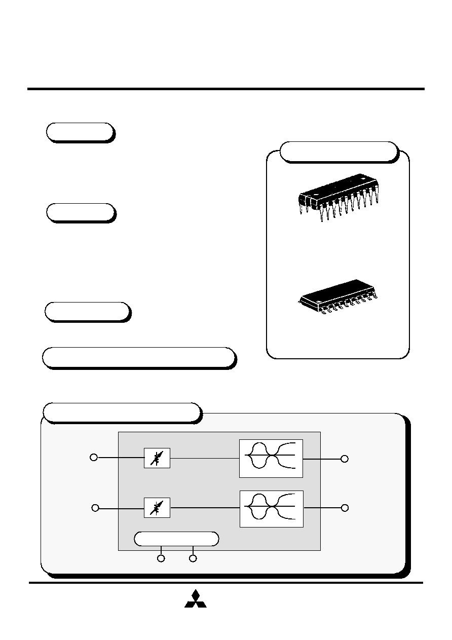
MITSUBISHI SOUND PROCESSOR
M62420SP/FP
SOUND CONTROLLER FOR TV
PRE
LIM
INA
RY
Notice ; This is not a final specification.
some parametric limits are subject to change.
ELECTRIC
MITSUBISHI
( / )
16
OUTLINE
M62420SP/FP is the tone and volume controller
which is controlled by I C bus.
This IC can apply the broad application because of
low noise and distortion.
1
2
20 P 4 B ( SP )
FEATURE
ÀTONE(Bass/Treble) control and 1dB step
volume control are enabled .
ÀLow noise and low distortion .
V
NO
= 4.5ÁVrms, CTHD=0.1% max
ÀControlling by serial data in conformity to the
I C bus format .
ÀTV, Mini-Stereo , etc
ÀSupply voltage range 8.5~9.5V (analog) 4.5~5.5V (digital)
ÀRated supply voltage 9V (analog) 5V (digital)
VOLUME
Lch IN
PACKAGE OUTLINE
SCL
SDA
Rch IN
Lch OUT
Rch OUT
PITCH : 1.78 mm
SIZE : 19.0 mm X 6.3 mm X 3.3 mm
I C BUS INTERFACE
Tone and Volume Controller by I C Bus System
2
APPLICATION
RECOMMENDED OPERATING CONDITION
SYSTEM BLOCK DIAGRAM
VOLUME
TONE CONTROL
BASS TREBLE
TONE CONTROL
BASS TREBLE
1
2
2
M62420SP/FP
20 P 2 N ( FP )
PITCH : 1.27 mm
SIZE : 5.3 mm X 12.6 mm X 1.8 mm
MITSUBISHI SOUND PROCESSOR
M62420SP/FP
SOUND CONTROLLER FOR TV
PRELIMINARY
Notice ; This is not a final specification.
some parametric limits are subject to change.
ELECTRIC
MITSUBISHI
( / )
16
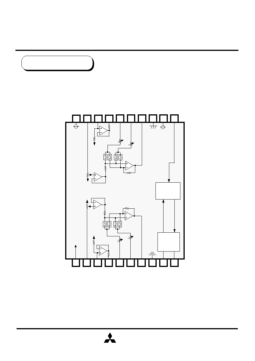
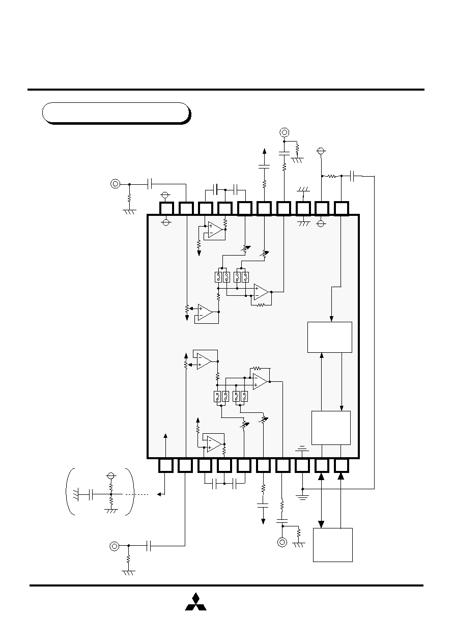
BLOCK DIAGRAM
2
DGND
AVDD
AGND
CH1 IN
CH2 IN
SDA
SCL
OUT2
BASS1
TRE1
OUT1
DVDD
SIMIN 1
SIMOUT 1
BASS2
TRE2
SIMIN 2
SIMOUT2
RESET
REF
5
6
7
8
9
10
11
12
13
14
15
16
17
18
19
20
1
2
3
4
ref
ref
TONE
AMP1
VOLAMP1
VR1
6.5K
S1 S3S5 S7
VR3
VR5
136K
ref
1.8K
SIMAMP1
ref
TONE
AMP2
VOLAMP2
VR2
S2 S4 S6 S8
VR6
VR4
136K
ref
1.8K
SIMAMP2
6.5K
6.5K
6.5K
I C BUS
INTER
FACE
2
CONTROL
LOGIC
MITSUBISHI SOUND PROCESSOR
M62420SP/FP
SOUND CONTROLLER FOR TV
PRELIMINARY
Notice ; This is not a final specification.
some parametric limits are subject to change.
ELECTRIC
MITSUBISHI
( / )
16
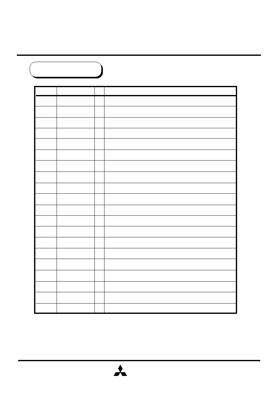
PIN DESCRIPTION
3
PIN No.
PIN NAME
DESCRIPTION
1
2
3
4
5
6
7
8
9
10
DGND
DVDD
CH1 IN
SDA
SCL
VOL OUT1
AVDD
AGND
REF
CH2 IN
VOL OUT2
11
12
13
14
15
16
17
18
19
20
Digital GND
I/O
I
I
O
I
I
O
I/O
I
O
I
I
O
I
I
BASS1
TRE1
SIMIN 1
SIMOUT 1
BASS2
TRE2
SIMIN 2
SIMOUT2
Input terminal (ch1)
Pin for capaciter of simurated inductor 1
Pin for capaciter of simurated inductor 1
Pin for capaciter of ch1-side bass setting
Pin for capaciter of ch1-side treble setting
Output terminal (ch1)
Reference voltage terminal for anarog
I/ O terminal of DATA I C bus format
2
Input terminal of CLOCK I C bus format
2
RESET
I
RESET terminal of built-in logic circuit
VDD for digital circuit
GND for analog circuit
Output terminal (ch2)
Pin for capaciter of ch2-side treble setting
Input terminal (ch2)
Pin for capaciter of simurated inductor 2
Pin for capaciter of simurated inductor 2
Pin for capaciter of ch2-side bass setting
VCC for analog circuit
I
I
I
I
I
MITSUBISHI SOUND PROCESSOR
M62420SP/FP
SOUND CONTROLLER FOR TV
PRELIMINARY
Notice ; This is not a final specification.
some parametric limits are subject to change.
ELECTRIC
MITSUBISHI
( / )
16
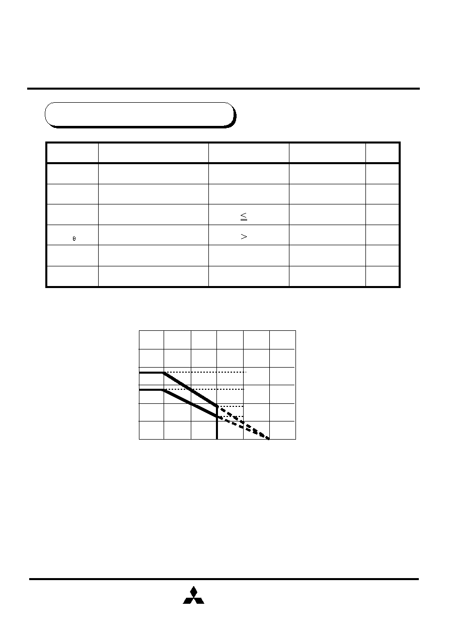
ABSOLUTE MAXIMUM RATINGS
4
Power dissipation pd [mW]
Ambient temperature Ta [░C]
0
200
600
0
25
50
75
100
125
150
750mW
400
800
1000
375mW
SYMBOL
Pd
Topr
Tstg
-20~+75
-40~+125
V
mW
░C
░C
PARAMETER
CONDITION
LIMITS
UNIT
Power dissipation
Operating temperature
750
mW/░C
DVdd
10.0
7.0
V
Analog supply voltage
AVdd
K
7.5
Digital supply voltage
Thermal Derating ratio
Strage temperature
Thermal Derating
Ta 25░C
Ta 25░C
275mW
550mW
SP
FP
MITSUBISHI SOUND PROCESSOR
M62420SP/FP
SOUND CONTROLLER FOR TV
PRELIMINARY
Notice ; This is not a final specification.
some parametric limits are subject to change.
ELECTRIC
MITSUBISHI
( / )
16
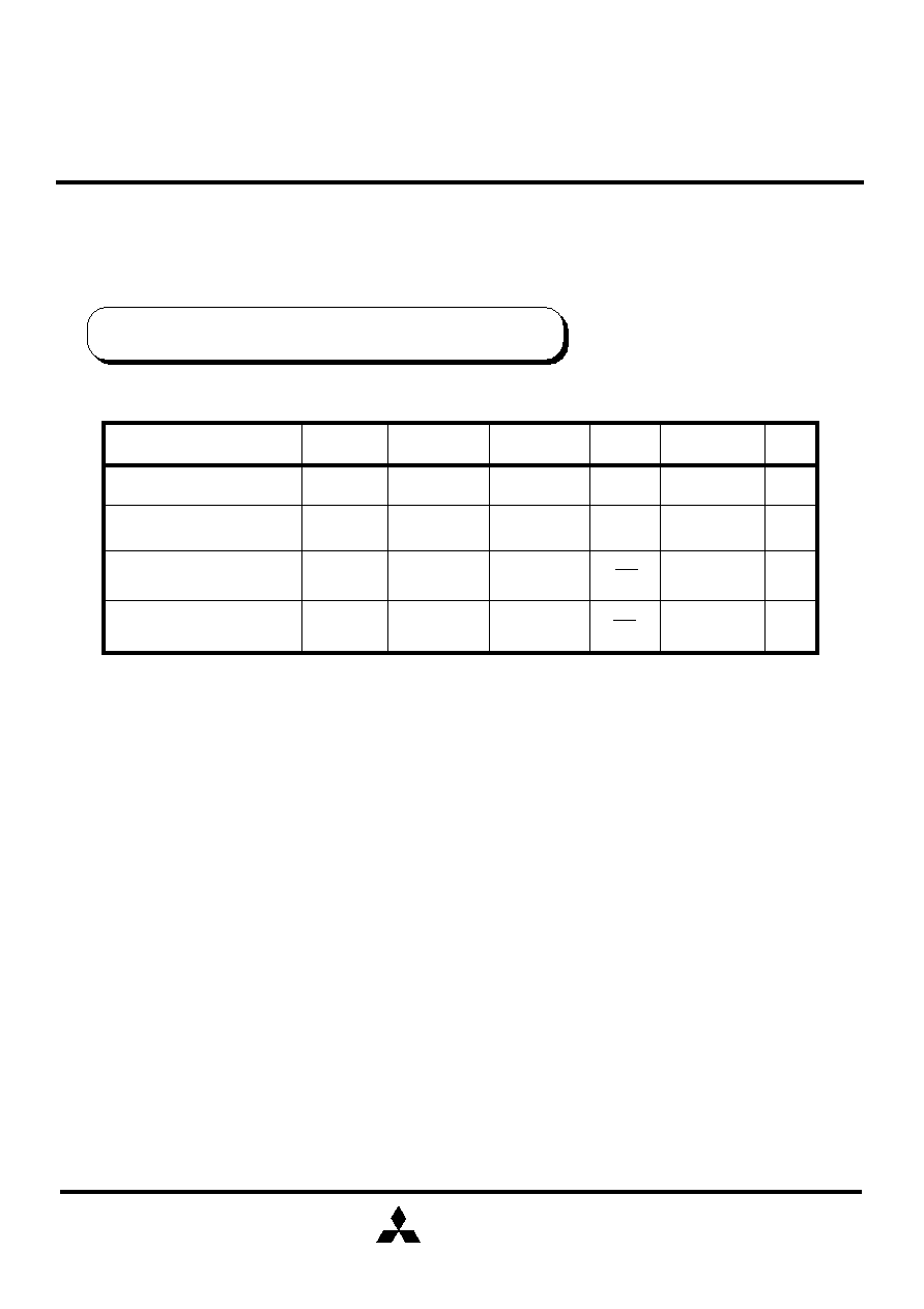
RECOMMENDED OPERATING CONDITION
( Ta=25░C unless otherwise noted )
5
MIN
TYP
MAX
AVDD
DVDD
9.0
9.5
8.5
5.0
5.5
4.5
VDD
0.7 DVDD
0
0.3 DVDD
V
V
V
V
VIH
VIL
SYMBOL
CONDITION
UNIT
ITEM
Analog
supply voltage
Digital
supply voltage
H level input voltage
L level input voltage
(logic circuit)
(logic circuit)

MITSUBISHI SOUND PROCESSOR
M62420SP/FP
SOUND CONTROLLER FOR TV
PRELIMINARY
Notice ; This is not a final specification.
some parametric limits are subject to change.
ELECTRIC
MITSUBISHI
( / )
16
( Ta=25░C, AVDD=9V,DVDD=5V and tone,bassboost=0dB
unless otherwise noted )
6
ELECTRIC CHARACTERISTICS
( 1 ) SUPPLY VOLTAGE
( 2 ) I / O CHARACTERISTICS
Min
typ
Max
Icc
10
mA
Idd
0
ÁA
ÀAVdd=9.0V
ÀDVdd= 5V
Àno signal input
Àmesure terminal=20 pin
20
2
Analog supply current
Digital supply current
SYMBOL
CONDITION
UNIT
ITEM
Àmesure terminal=12 pin
Àno signal input
LIMIT
Min
typ
Max
Maximum input voltage
3.2
Vrms
2.0
VIM
RL=10K
, THD=1%,f=1kHz
Output voltage
Vodc
Gain
Output noise voltage
Total harmonic distortion
THD
Vono
Gv
Channel separation
CT
7pin,14pin,
no signal
Vin=0dBm,FLAT,f=1kHz
2- 7PIN 19-14PIN gain
4.5
0
dB
V
%
dB
4.5
0.1
0.05
-100
RL=10K
Vo=0.5Vrms , RL=10K
7pin,14pin f=1kHz
30
4.65
4.35
2
-2
2,19pin input7,14pin output
JIS-A filter
no signal
Rg=10K
7,14pin
S:Vin=1Vrms,f=1kHz
M:Rg=10k
,JIS-A filter
Á Vrms
SYMBOL
CONDITION
ITEM
LIMIT
UNIT
ATT=-6dB
LPF=30kHz
-70

MITSUBISHI SOUND PROCESSOR
M62420SP/FP
SOUND CONTROLLER FOR TV
PRELIMINARY
Notice ; This is not a final specification.
some parametric limits are subject to change.
ELECTRIC
MITSUBISHI
( / )
16
7
( 3 ) TONE CHARACTERISTICS
12
Tone controll gain
(bass)
Gbassb
9
15
dB
-12
Gbassc
-15
-9
dB
12
Gtrebb
f=10KHz
9
15
dB
-12
Gtrebc
-15
-9
dB
Min
typ
Max
SYMBOL
CONDITION
UNIT
ITEM
LIMIT
Tone controll gain
(treble)
f=100Hz
( 4 ) VOLUME CHARACTERISTICS
-100
dB
ATTmax
f=1KHz, Vin=0dBm
2pin~7pin
19pin~14pin gain
0
dB
Maximum attenuation
ATTmin
Min
typ
Max
SYMBOL
CONDITION
UNIT
ITEM
LIMIT
Minimum attenuation
JIS-A filter
-108
-80
-1.5
1.5
MITSUBISHI SOUND PROCESSOR
M62420SP/FP
SOUND CONTROLLER FOR TV
PRELIMINARY
Notice ; This is not a final specification.
some parametric limits are subject to change.
ELECTRIC
MITSUBISHI
( / )
16
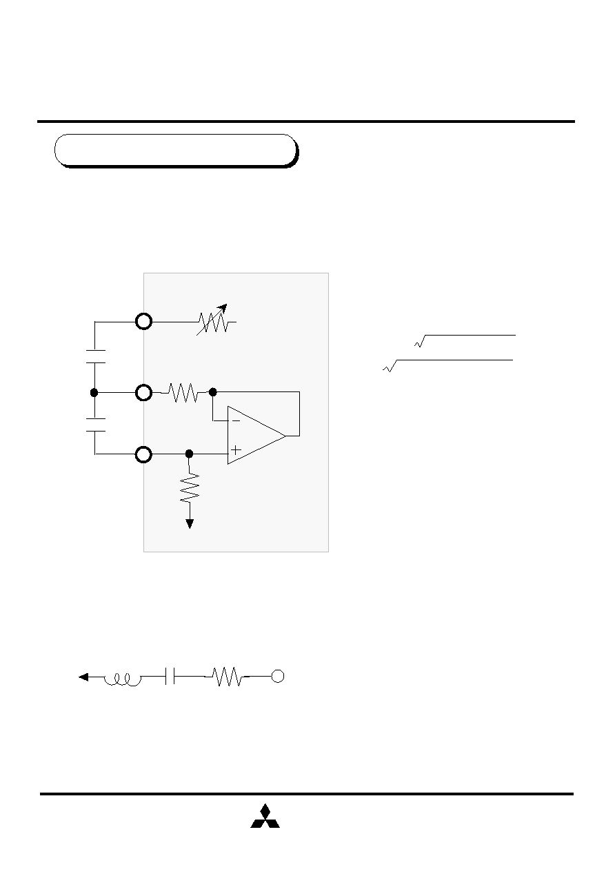
( 1 ) EQUIVARATION CIRCUIT OF TONE CONTROLL
FUNCTION EXPLANATION
The resonance circuit is able to consstruct by using built-in
amplifier for simurated inductor. (Shows the constant as
follow)
8
R3
C1
C2
FIG2. The equivalent circuit used L.
C1
L
R3
( EX ) BASS band ( f=100Hz )
R1=1.8K
, R2=136K
C1=0.47Á , C2=0.022Á
Center frequency
f0 = 1 / 2
C1 À C2 À R1 À R2 [Hz]
Q = ( C2 À R2 ) / ( C1 À R1 )
FIG1 is equal to FIG2.
The following relation is concluded.
Incide IC
R1
(=1.8K
)
R2
(=136K
)
SIMAMP
FIG1. The circuit used simurated inductor.
L=C2 À ER1 À ER2
ref
ref
MITSUBISHI SOUND PROCESSOR
M62420SP/FP
SOUND CONTROLLER FOR TV
PRELIMINARY
Notice ; This is not a final specification.
some parametric limits are subject to change.
ELECTRIC
MITSUBISHI
( / )
16
2
9
I C BUS INPUT DATA FORMAT
( 2 ) sub address
S
A
A
A P
starting term
( 1 ) slave
address
( 2 ) sub
address
( 3 ) data
( 1 ) slave address
subA6
subA5
subA4
subA3
subA2
subA1
subA0
subA7
empty slot
channel2
volume
mode
1: ON
0: OFF
1: ON
0: OFF
BASS
level
mode
TREBLE
level
mode
1: ON
0: OFF
1: ON
0: OFF
Input direction
acknowledge bit
ending term
The following slave address is assigned at this IC.
The following sub address is defined at this IC.
channel1
volume
mode
A6
A5
A4
A3
A2
A1
A0
R/W
1
0
0
0
0
0
0
MUTE
mode
1: ON
0: OFF
acknowledge bit
MITSUBISHI SOUND PROCESSOR
M62420SP/FP
SOUND CONTROLLER FOR TV
PRELIMINARY
Notice ; This is not a final specification.
some parametric limits are subject to change.
ELECTRIC
MITSUBISHI
( / )
16
10
subA3 : 0
subA2 : 0
subA0 : 0 , 1 , 1
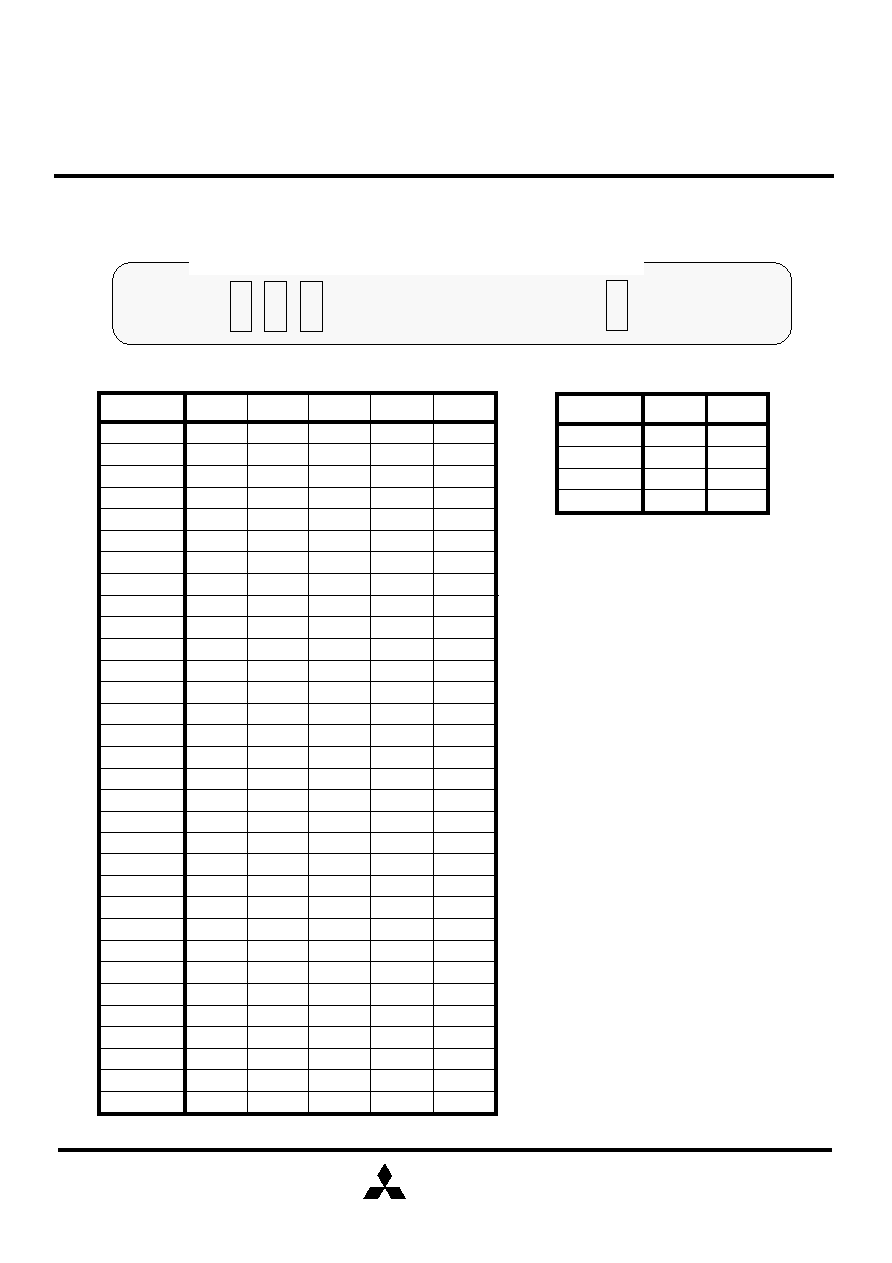
( 3 ) -1: volume control
volume code
The volume control is enabled at following condition.
subA1 : 1 , 0 , 1
(either bit is 1)
(both bits are 0)
*
2dB,3dB setting is
enabled at less than
42dB step.
D4
D3
D2
D1
D0
ATT
0dB
2dB
4dB
6dB
8dB
10dB
12dB
14dB
16dB
18dB
20dB
22dB
24dB
26dB
28dB
30dB
32dB
36dB
38dB
40dB
42dB
46dB
50dB
34dB
54dB
58dB
62dB
66dB
70dB
74dB
78dB
dB
H
L
H
L
H
L
H
L
H
L
H
L
H
L
H
L
H
L
H
L
H
L
H
L
H
L
H
L
H
L
H
L
H
H
L
L
H
H
L
L
H
H
L
L
H
H
L
L
H
H
L
L
H
H
L
L
H
H
L
L
H
H
L
L
H
H
H
H
L
L
L
L
H
H
H
H
L
L
L
L
H
H
H
H
L
L
L
L
H
H
H
H
L
L
L
L
H
H
H
H
H
H
H
H
L
L
L
L
L
L
L
L
H
H
H
H
H
H
H
H
L
L
L
L
L
L
L
L
H
H
H
H
H
H
H
H
H
H
H
H
H
H
H
H
L
L
L
L
L
L
L
L
L
L
L
L
L
L
L
L
D5
D6
ATT
0dB
1dB
*
2dB
*
3dB
H
L
H
L
H
H
L
L

MITSUBISHI SOUND PROCESSOR
M62420SP/FP
SOUND CONTROLLER FOR TV
PRELIMINARY
Notice ; This is not a final specification.
some parametric limits are subject to change.
ELECTRIC
MITSUBISHI
( / )
16
11
( 4 ) -2 : tone level control
tone code
subA1 : 0
subA0 : 0
subA2 : 0 , 1 , 1
The tone level controlling is enabled at following condition.
subA3 : 1 , 0 , 1
(either bit is 1)
(both bits are 0)
D7
D6
D5
D4
TREBLE
0dB
-2dB
-4dB
-6dB
-8dB
-10dB
-12dB
H
H
H
H
H
H
L
L
L
L
L
2dB
4dB
6dB
8dB
10dB
12dB
BASS
D3
D2
D1
D0
( 5 ) -3 : Mute mode
subA4 : 1
subA1 : no definition
subA0 : no definition
subA3 : no definition
subA2 : no definition
L
L
H
H
H
H
H
H
L
L
L
L
L
L
L
H
L
L
H
H
L
L
L
H
H
L
L
H
L
H
L
H
L
H
L
H
L
H
L
H
L
H
H
H
H
H
H
L
L
L
L
L
L
L
H
H
H
H
H
H
L
L
L
L
L
L
L
H
L
L
H
H
L
L
L
H
H
L
L
H
L
H
L
H
L
H
L
H
L
H
L
H
L
HHHH
LHHH
HLLL
non-used code
The mute mode is enabled at following condition.
MITSUBISHI SOUND PROCESSOR
M62420SP/FP
SOUND CONTROLLER FOR TV
PRELIMINARY
Notice ; This is not a final specification.
some parametric limits are subject to change.
ELECTRIC
MITSUBISHI
( / )
16
12
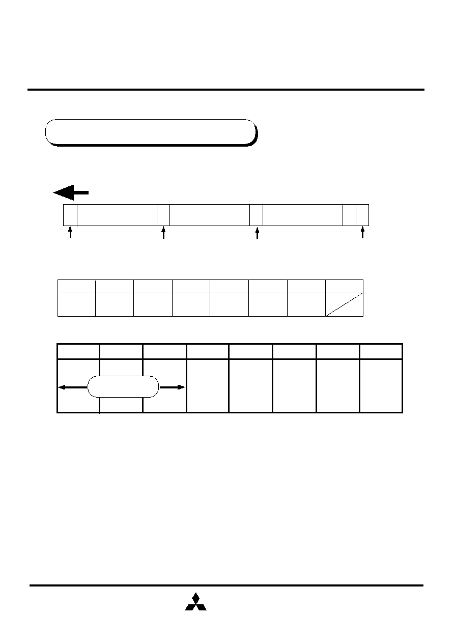
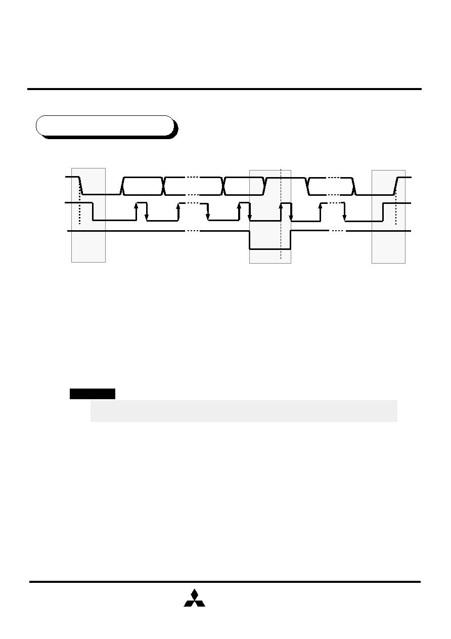
CAUTION
S D A (IN)
S C L
S D A (OUT)
1
2 ~ 7
8
9
S
P
ACK
start
acknowledge
stop
start
This term is defined by SDA(in) falling edge at SCL H .
This term is defined by SDA(in) rising edge at SCL H .
stop
The SDA(IN) level never change at SCK=H
except start and stop .
The SDA(IN) is enabled at SCL rising edge and H .
data transmisson
acknowledge
Transmitter must send H during ninth clock pulse of SCL .
The case of finished receiving , the receiver replies L synchronized to
falling edge of eighth pulse . And restart receiving the transmitted data
synchronized to falling edge of ninth pulse .
DATA and CLOCK
MITSUBISHI SOUND PROCESSOR
M62420SP/FP
SOUND CONTROLLER FOR TV
PRELIMINARY
Notice ; This is not a final specification.
some parametric limits are subject to change.
ELECTRIC
MITSUBISHI
( / )
16
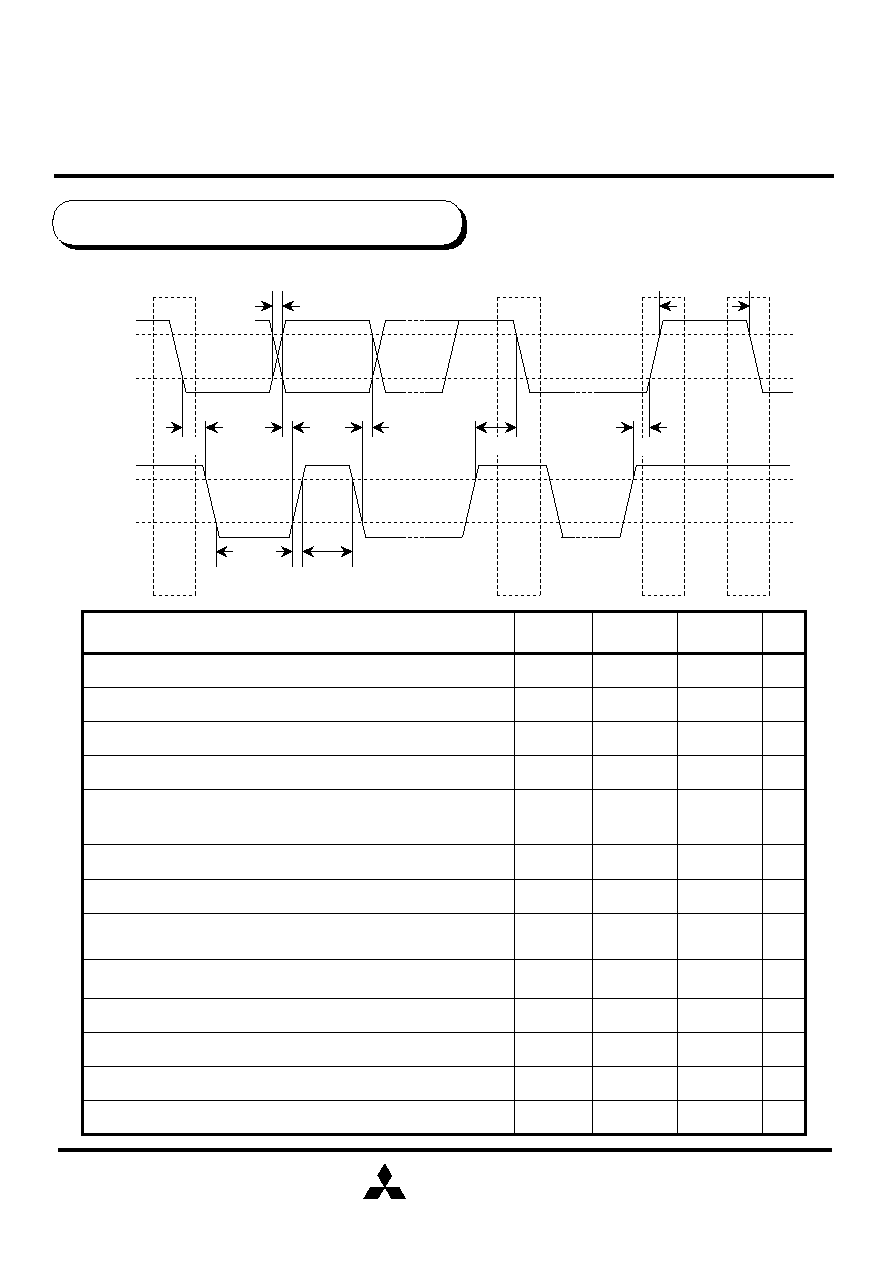
BUS LINE TIMMING SPECIFICATION
13
parameter
symbol
MIN
MAX
units
min. input low voltage
max. input high voltage
SCL clock frequency
Time the bus must be free before a new transmission can start
Hold time start condition. After this period the first clock pulse
is generated
The LOW preiod of the clock
The HIGH period of the clock
Set up time for start condition ( Only relevant for a repeated
start condition )
Hold time DATA
Set -up time DATA
Rise time of both SDA and SCL lines
Fall time of both SDA and SCL lines
Set-up time for stop condition
f
SCL
t
BUF
t
HD:STA
t
LOW
t
HIGH
t
SU:STA
t
HD:DAT
t
SU:DAT
t
R
t
F
t
SU:STO
V
IL
V
IH
-0.5
1.5
V
3.0
5.5
V
0
100
KHz
4.7
4.0
4.7
4.0
4.7
0
250
1000
300
4.0
Á s
ns
ns
ns
Á s
Á s
Á s
Á s
Á s
Á s
-
-
-
-
-
-
-
-
-
-
t
R,
t
F
t
BUF
t
LOW
t
HIGH
t
HD:DAT
t
SU:DAT
SDA
SCL
V
IL
V
IH
V
IL
V
IH
t
HD:STA
t
SU:STA
t
SU:STO
S
S
P
S
MITSUBISHI SOUND PROCESSOR
M62420SP/FP
SOUND CONTROLLER FOR TV
PRELIMINARY
Notice ; This is not a final specification.
some parametric limits are subject to change.
ELECTRIC
MITSUBISHI
( / )
16
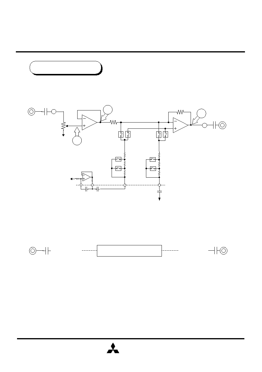
14
LEVEL DIAGRAM
VOLAMP1
6.5K
TONEAMP1
ref
136K
1.8K
ref
G1
0dB~ -
dB
G1
G2
-12dB~ +12dB
6.5K
CH1 IN
CH2 IN
CH1 OUT
CH2 OUT
same to CH1
MITSUBISHI SOUND PROCESSOR
M62420SP/FP
SOUND CONTROLLER FOR TV
PRELIMINARY
Notice ; This is not a final specification.
some parametric limits are subject to change.
ELECTRIC
MITSUBISHI
( / )
16
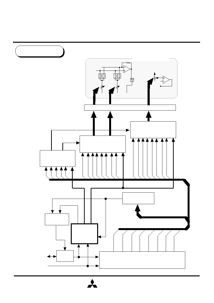
<D4>
SDA
<D3>
<D2>
<D1>
<D0>
<D5>
<D6>
<D7>
SCL
LOGIC CIRCUIT
Shift register
Level shifter
Decoder, latch
for volume control
Sub-address
latch circuit
<D4>
<D3>
<D2>
<D1>
<D0>
<D4>
<D3>
<D2>
<D1>
<D0>
Slave address
compare circuit
Bi-direct
control
<D6>
<D5>
<D7>
<D4>
<D3>
<D2>
<D1>
<D0>
<D6>
<D5>
<D7>
TONE
AMP1
ref
VOLAMP1
ANALOG BLOCK
15
Decoder, latch
for tone control
Acknowledge
generator
Timing
generator
MITSUBISHI SOUND PROCESSOR
M62420SP/FP
SOUND CONTROLLER FOR TV
PRELIMINARY
Notice ; This is not a final specification.
some parametric limits are subject to change.
ELECTRIC
MITSUBISHI
( / )
16
16
APPLICATION EXAMPLE
MPU
VCC
AGND
DGND
2.2Á F
2.2Á F
2.2Á F
2.2ÁF
470Á F
IN2
IN1
OUT1
OUT2
ref
ref
0.033Á F
0.47Á F
0.022Á F
4.7K
Reference circuit
example
1.8K
5
6
7
8
9
10
11
12
13
14
15
16
17
18
19
20
1
2
3
4
ref
ref
TONE
AMP1
VOLAMP1
VR1
6.5K
S1 S3S5 S7
VR3
VR5
136K
ref
1.8K
SIMAMP1
ref
TONE
AMP2
VOLAMP2
VR2
S2 S4S6 S8
VR6
VR4
136K
ref
1.8K
SIMAMP2
6.5K
6.5K
6.5K
0.033Á F
0.47Á F
0.022Á F
1.8K
I C BUS
INTER
FACE
2
CONTROL
LOGIC
Reference
voltage
DVDD
1000pF
100K
430
430
4.7K
10K
10K
10K
10K