September 2001
1
MIC4827
MIC4827
Micrel
MIC4827
Low Input Voltage, 180V
PP
Output Voltage, EL Driver
Final Information
General Description
Micrel's MIC4827 is a high output voltage, DC to AC con-
verter, designed for driving EL (Electroluminescent) lamps.
The device operates from an input voltage range of 1.8V to
5.5V, making it suitable for 1-cell Li Ion and 2- or 3-cell
alkaline/NiCad/NiMH battery applications. The MIC4827 con-
verts a low voltage DC input to a 180V
PP
AC output signal that
drives the EL lamp.
The MIC4827 is comprised of two stages: a boost stage, and
an H-bridge, lamp driver, stage. The boost stage steps the
input voltage up to +90V. The H-bridge stage then alternately
switches the +90V output to each terminal of the EL lamp,
thus creating a 180V
PP
AC signal to drive the EL lamp and
generate light.
The MIC4827 features separate oscillators for the boost- and
H-bridge stages. External resistors independently set the
operating frequency of each stage. This flexibility allows the
EL lamp circuit to be optimized for maximum efficiency and
brightness.
The MIC4827 uses a single inductor and a minimum number
of external components, making it ideal for portable, space-
sensitive applications.
The MIC4827 is available in an 8-pin MSOP package with an
ambient temperature range of 40
°
C to +85
°
C.
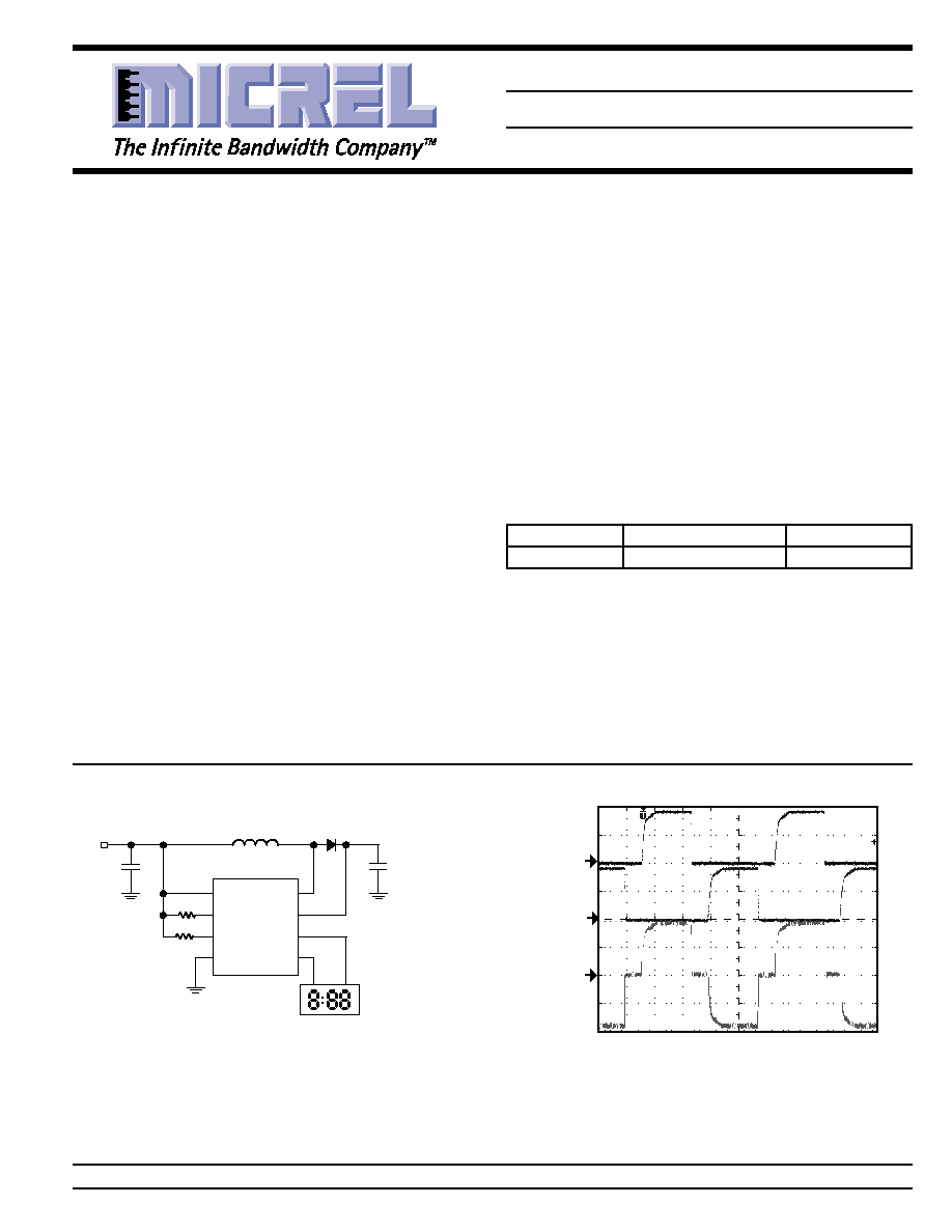
Typical Application
332k
3.32M
C
OUT
0.033
µ
F/100V
D1
1N4148
L1
220
µ
H
2in
2
EL LAMP
1
5
6
8
7
2
3
4
SW
CS
VA
VB
VDD
RSW
REL
GND
MIC4827
C
IN
10
µ
F
V
IN
Features
· 1.8V to 5.5V DC input voltage
· 180V
PP
regulated AC output waveform
· Independently adjustable EL lamp frequency
· Independently adjustable boost converter frequency
· 0.1
µ
A shutdown current
Applications
· LCD panel backlight
· Cellular phones
· PDAs
· Pagers
· Calculators
· Remote controls
· Portable phones
Ordering Information
Part Number
Ambient Temp. Range
Package
MIC4827BMM
40
°
C to +85
°
C
MSOP-8
Micrel, Inc. · 1849 Fortune Drive · San Jose, CA 95131 · USA · tel + 1 (408) 944-0800 · fax + 1 (408) 944-0970 · http://www.micrel.com
TIME (2ms/div)
V
B
(50V/div)
V
A
(50V/div)
V
A
--
V
B
(50V/div)
High Voltage EL Driver
MIC4827
Micrel
MIC4827
2
September 2001
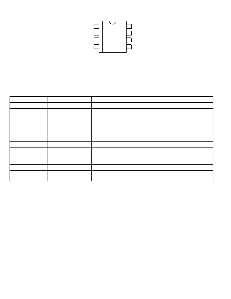
Pin Configuration
1
VDD
RSW
REL
GND
8
VA
VB
CS
SW
7
6
5
2
3
4
8-Pin MSOP Package (MM)
Pin Description
Pin Number
Pin Name
Pin Function
1
VDD
Supply (Input): 1.8V to 5.5V for internal circuitry.
2
RSW
Switch Resistor (External Component): Set switch frequency of the internal
power MOSFET by connecting an external resistor to VDD. Connecting the
external resistor to GND disables the switch oscillator and shuts down the
device.
3
REL
EL Resistor (External Component): Set EL frequency of the internal H-bridge
driver by connecting an external resistor to VDD. Connecting the external
resistor to GND disables the EL oscillator.
4
GND
Ground Return.
5
SW
Switch Node (Input): Internal high-voltage power MOSFET drain.
6
CS
Regulated Boost Output (External Component): Connect to the output
capacitor of the boost regulator and connect to the cathode of the diode.
7
VB
EL Output: Connect to one end of the EL lamp. Polarity is not important.
8
VA
EL Output: Connect to the other end of the EL lamp. Polarity is not impor-
tant.
September 2001
3
MIC4827
MIC4827
Micrel
Absolute Maximum Ratings
(Note 1)
Supply Voltage (V
DD
) ....................................... 0.5V to 6V
Output Voltage (V
CS
) ................................... 0.5V to 100V
Frequency Control Voltage (V
RSW,
V
REL
) ... 0.5V to (V
DD
+0.3V)
Power Dissipation @ T
A
= 85
°
C ............................. 200mW
Storage Temperature (T
S
) ....................... 65
°
C to +150
°
C
ESD Rating .............................................................. Note 3
Operating Ratings
(Note 2)
Supply Voltage (V
DD
) .................................. +1.8V to +5.5V
Lamp Drive Frequency (f
EL
) ...................... 60Hz to 1000Hz
Switching Transistor Frequency (f
SW
) ........ 8kHz to 200kHz
Ambient Temperature (T
A
) ......................... 40
°
C to +85
°
C
Package Thermal Resistance
MSOP
(
JA
) ....................................................... 206
°
C/W
Electrical Characteristics
V
IN
= V
DD
= 3.0V, R
SW
= 560K
, R
EL
= 1.0M
. T
A
= 25
°
C unless otherwise specified. Bold values indicate 40
°
C
T
A
+85
°
C
Symbol
Parameter
Condition
Min
Typ
Max
Units
R
DS(ON)
On-resistance of switching transistor
I
SW
= 100 mA, V
CS
= 85V
3.8
7.0
V
CS
Output voltage regulation
V
DD
= 1.8V to 5.5V
85
90
95
V
83
97
V
V
A
V
B
Output peak-to-peak voltage
V
DD
= 1.8V to 5.5V
170
180
190
V
166
194
V
V
EN-L
Input low voltage (turn-off)
V
DD
= 1.8V to 5.5V
0.5
V
V
EN-H
Input high voltage (turn-on)
V
DD
= 1.8V to 5.5V
V
DD
0.5
V
I
SD
Shutdown current, Note 4
R
SW
= LOW; R
EL
= LOW;
0.01
0.1
µ
A
V
DD
= 5.5V
0.5
µ
A
I
VDD
Input supply current
R
SW
= HIGH; R
EL
= HIGH;
21
75
µ
A
V
CS
= 85V; V
A
, V
B
OPEN
I
CS
Boosted supply current
R
SW
= HIGH; R
EL
= HIGH;
200
400
µ
A
V
CS
= 85V; V
A
, V
B
OPEN
I
IN
Input current including inductor
V
IN
= V
DD
= 1.8V
28
mA
current
(See Test Circuit)
f
EL
V
A
V
B
output drive frequency
285
360
435
Hz
f
SW
Switching transistor frequency
53
66
79
kHz
D
Switching transistor duty cycle
90
%
Note 1.
Exceeding the absolute maximum rating may damage the device.
Note 2.
The device is not guaranteed to function outside its operating rating.
Note 3.
Devices are ESD sensitive. Handling precautions recommended.
Note 4.
Shutdown current is defined as the sum of current going into pin 1, 5, and 6 when the device is disabled.
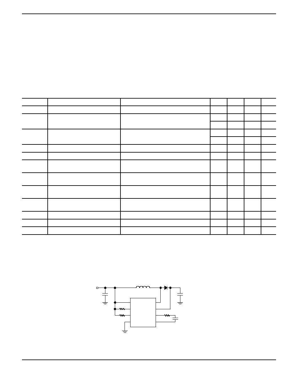
Test Circuit
C
OUT
0.033
µ
F/100V
D1
1N4148
L1
220
µ
H
1
5
6
8
7
2
3
4
SW
CS
VA
VB
VDD
RSW
REL
GND
MIC4827
C
IN
10
µ
F
10nF
V
IN
562k
3.32M
100
MIC4827
Micrel
MIC4827
4
September 2001
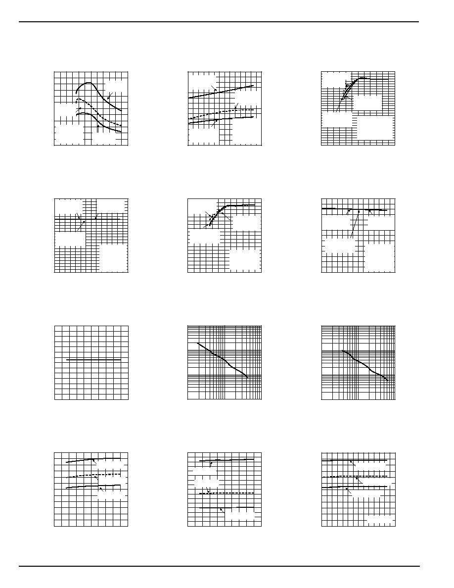
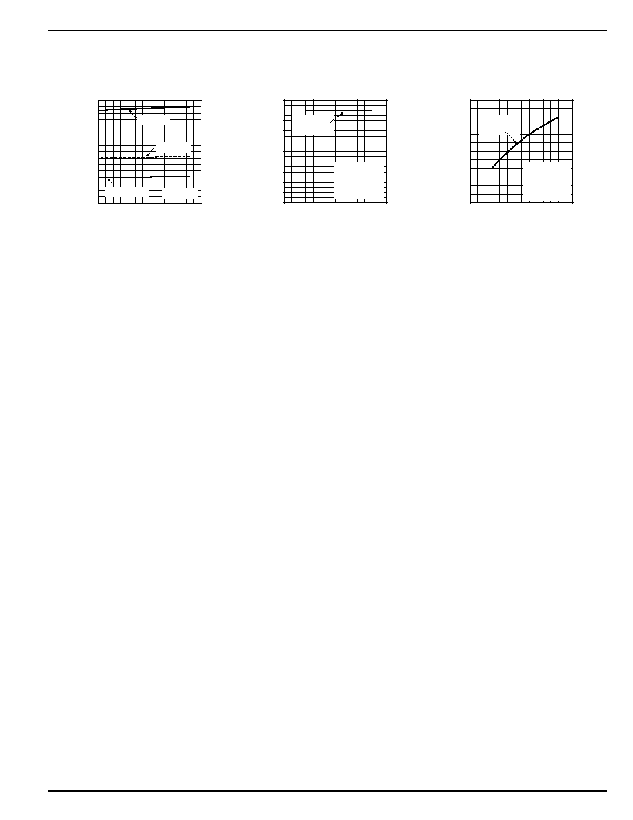
Typical Characteristics
0
10
20
30
40
50
60
0
1
2
3
4
5
6
INPUT CURRENT (mA)
INPUT VOLTAGE (V)
Total Input Current
vs. Input Voltage
R
SW
= 332k
R
EL
= 3.32M
R
SW
= 442k
R
EL
= 2M
R
SW
= 562k
R
EL
= 1M
Lamp = 2in
2
L = 220
µ
H
C
OUT
= 0.1
µ
F
D = BAV20WS
0
10
20
30
40
50
60
70
-40 -20
0
20
40
60
80 100
INPUT CURRENT (mA)
TEMPERATURE (
°
C)
Total Input Current
vs. Temperature
R
SW
= 332k
R
EL
= 3.32M
R
SW
=
442k
R
EL
=
2M
R
SW
= 562k
R
EL
= 1M
V
IN
= 3.0V
Lamp
= 2in
2
L = 220
µ
H
C
OUT
= 0.1
µ
F
D = BAV20WS
0
20
40
60
80
100
120
140
160
180
200
0
1
2
3
4
5
6
OUTPUT VOLTAGE (V
P-P
)
INPUT VOLTAGE (V)
R
SW
= 442k
Output Voltage
vs. Input Voltage
R
SW
= 332k
R
EL
= 3.32M
R
SW
= 562k
R
EL
= 1M
Lamp = 2in2
L = 220
µ
H
C
OUT
= 0.1
µ
F
D = BAV20WS
R
EL
= 2M
0
20
40
60
80
100
120
140
160
180
200
220
240
-40 -20
0
20
40
60
80 100
OUTPUT VOLTAGE (V
PP
)
TEMPERATURE (
°
C)
Output Voltage
vs. Temperature
R
SW
= 332k
R
EL
= 3.32M
R
SW
= 562k
R
EL
= 1M
V
IN
= 3.0V
Lamp
= 2in
2
L = 220
µ
H
C
OUT
= 0.1
µ
F
D = BAV20WS
R
SW
= 442k
R
EL
= 2M
30
40
50
60
70
80
90
100
-40 -20
0
20
40
60
80 100
V
CS
(V
AVG
)
TEMPERATURE (
°
C)
CS Voltage
vs. Temperature
R
SW
= 332k
R
EL
= 3.32M
R
SW
=
442k
R
EL
=
2M
R
SW
= 562k
R
EL
= 1M
V
IN
= 4.0V
Lamp
= 2in
2
L = 220
µ
H
C
OUT
= 0.1
µ
F
D = BAV20WS
0
1
2
3
4
5
6
7
1
2
3
4
5
6
SWITCH RESISTANCE (
)
INPUT VOLTAGE (V)
Switch Resistance
vs. Input Voltage
10
100
1000
10000
0.1
1
10
EL FREQUENCY (Hz)
EL RESISTOR (M
)
EL Frequency
vs. EL Resistor
1
10
100
1000
100
1000
10000
SWITCHING FREQUENCY (kHz)
SWITCH RESISTOR (k
)
Switching Frequency
vs. Switch Resistor
0
20
40
60
80
100
120
-40 -20
0
20
40
60
80 100
FREQUENCY (KHz)
TEMPERATURE (
°
C)
Switching Frequency
vs. Temperature
R
SW
= 332k
V
IN
= 3.0V
R
SW
= 442k
R
SW
= 562k
0
20
40
60
80
100
120
1
2
3
4
5
6
SWITCHING FREQUENCY (Hz)
INPUT VOLTAGE (V)
Switching Frequency
vs. Input Voltage
R
SW
= 562k
R
SW
= 442k
R
SW
= 332k
0
10
20
30
40
50
60
70
80
90
100
0
1
2
3
4
5
6
V
CS
(V
AVG
)
INPUT VOLTAGE (V)
CS Voltage
vs. Input Voltage
R
SW
= 332k
R
EL
= 3.32M
R
SW
= 442k
R
EL
= 2M
R
SW
= 562k
R
EL
= 1M
Lamp = 2in
2
L = 220
µ
H
C
OUT
= 0.1
µ
F
D = BAV20WS
0
50
100
150
200
250
300
350
400
1
2
3
4
5
6
EL FREQUENCY (Hz)
INPUT VOLTAGE (V)
EL Frequency
vs. Input Voltage
R
EL
= 1M
R
EL
= 2M
R
EL
= 3.32M
September 2001
5
MIC4827
MIC4827
Micrel
0
50
100
150
200
250
300
350
400
-40 -20
0
20
40
60
80 100
FREQUENCY (KHz)
TEMPERATURE (
°
C)
EL Frequency
vs. Temperature
R
SW
=1M
V
IN
= 3.0V
R
SW
= 2M
R
SW
= 3.32M
0
20
40
60
80
100
120
140
160
180
200
0
1
2
3
4
5
6
7
OUTPUT VOLTAGE (V
PP
)
LAMP SIZE (sq. in.)
Output Voltage
vs. Lamp Size
R
SW
= 332k
R
EL
= 3.32M
V
IN
= 3.0V
L = 220
µ
H
C
OUT
= 0.1
µ
F
D = BAV20WS
0
5
10
15
20
25
30
0
1
2
3
4
5
6
7
INPUT CURRENT (mA)
LAMP SIZE (sq. in.)
Total Input Current
vs. Lamp Size
R
SW
= 332k
R
EL
= 3.32M
V
IN
= 3.0V
L = 220
µ
H
C
OUT
= 0.1
µ
F
D = BAV20WS
MIC4827
Micrel
MIC4827
6
September 2001
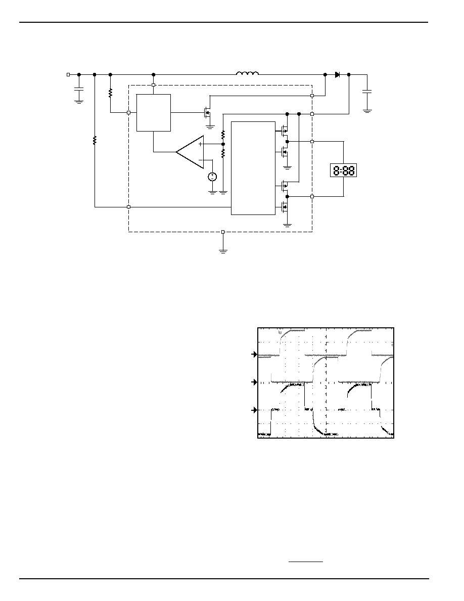
Block Diagram
Q
1
Q
2
/Q
3
/Q
4
EL
Oscillator
GND
V
REF
4
VB
EL LAMP
7
VA
8
CS
6
SW
C
OUT
D1
L1
220
µ
H
5
V
DD
1
RSW
R
SW
C
IN
2
REL
R
EL
3
Switch
Oscillator
V
IN
Functional Description
Overview
The MIC4827 is a high-voltage EL driver with an AC output
voltage of 180V peak-to-peak capable of driving EL lamps up
to 6in
2
.
Input supply current for the MIC4827 is typically 21
µ
A
with a typical shutdown current of 10nA. The high voltage EL
driver has two internal oscillators to control the switching
MOSFET and the H-bridge driver. Both of the internal oscil-
lators' frequencies can be individually programmed through
the external resistors to maximize the efficiency and the
brightness of the lamps.
Regulation
Referring to Figure 1, initially power is applied to V
DD
. The
internal feedback voltage is less than the reference voltage
causing the internal comparator to go low which enables the
switching MOSFET's oscillator. When the switching MOSFET
turns on, current flows through the inductor and into the
switch. The switching MOSFET will typically turn on for 90%
of the switching frequency. During the on-time, energy is
stored in the inductor. When the switching MOSFET turns off,
current flowing into the inductor forces the voltage across the
inductor to reverse polarity. The voltage across the inductor
rises until the external diode conducts and clamps the voltage
at V
OUT
+ V
D1
. The energy in the inductor is then discharged
into the C
OUT
capacitor. The internal comparator continues to
turn the switching MOSFET on and off until the internal
feedback voltage is above the reference voltage. Once the
internal feedback voltage is above the reference voltage, the
internal comparator turns off the switching MOSFET's oscil-
lator.
When the EL oscillator is enabled, V
A
and V
B
switch in
opposite states to achieve a 180V peak-to-peak AC output
signal. The external resistor that connects to the REL pin
determines the EL frequency.
TIME (2ms/div)
V
B
(50V/div)
V
A
(50V/div)
V
A
--
V
B
(50V/div)
V
IN
= 3.0V
L = 220
µ
H
C
OUT
= 0.033
µ
F
Lamp = 2in
2
R
SW
= 442k
R
EL
= 2M
Figure 2. 108Hz Typical Output Waveform
Switching Frequency
The switching frequency of the converter is controlled via an
external resistor between RSW pin and VDD pin of the
device. The switching frequency increases as the resistor
value decreases. For resistor value selections, see the "Typi-
cal Characteristics: Switching Frequency vs. Switch Resis-
tor" or use the equation below. The switching frequency
range is 8kHz to 200kHz, with an accuracy of
±
20%.
f
(kHz)
36
R
(M )
SW
SW
=
Figure 1. MIC4827 Block Diagram
September 2001
7
MIC4827
MIC4827
Micrel
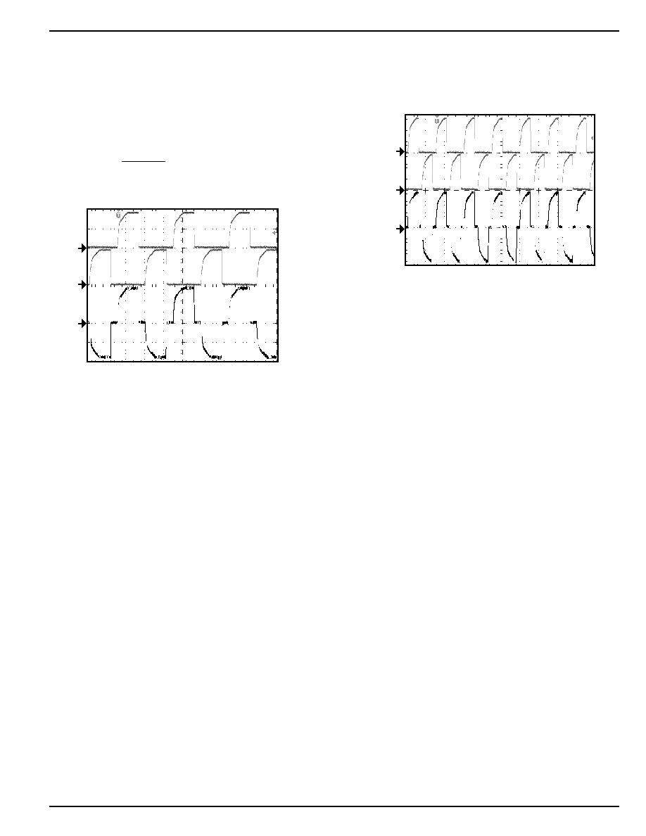
EL Frequency
The EL lamp frequency is controlled via an external resistor
connected between REL pin and VDD pin of the device. The
lamp frequency increases the resistor value decreases. For
resistor value selections, see the "Typical Characteristics: EL
Frequency vs. EL Resistor" or use the equation below. The
switching frequency range is 60Hz to 1000Hz, with an accu-
racy of
±
20%.
f
(Hz)
360
R
(M )
EL
EL
=
TIME (2ms/div)
V
IN
= 3.0V
L = 220
µ
H
C
OUT
= 0.033
µ
F
Lamp = 2in
2
R
SW
= 562k
R
EL
= 1M
V
B
(50V/div)
V
A
(50V/div)
V
A
--
V
B
(50V/div)
Figure 3. 180Hz Output Waveform
In general, as the EL lamp frequency increases, the amount
of current drawn from the battery will increase. The color of
the EL lamp and the intensity are dependent upon its fre-
quency.
TIME (2ms/div)
V
B
(50V/div)
V
A
(50V/div)
V
A
--
V
B
(50V/div)
Figure 4. 360Hz Output Waveform
Enable Function
The enable function of the MIC4827 is implemented by
switching the R
SW
and R
EL
resistor between ground and V
DD
.
When R
SW
and R
EL
are connected to ground, the switch and
the EL oscillators are disabled; therefore the EL driver be-
comes disabled. When these resistors connect to V
DD
, both
the oscillators will function and the EL driver is enabled.
MIC4827
Micrel
MIC4827
8
September 2001
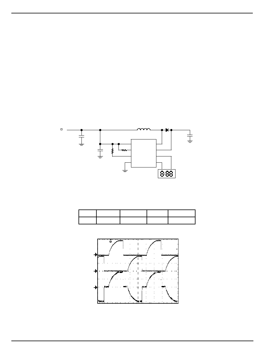
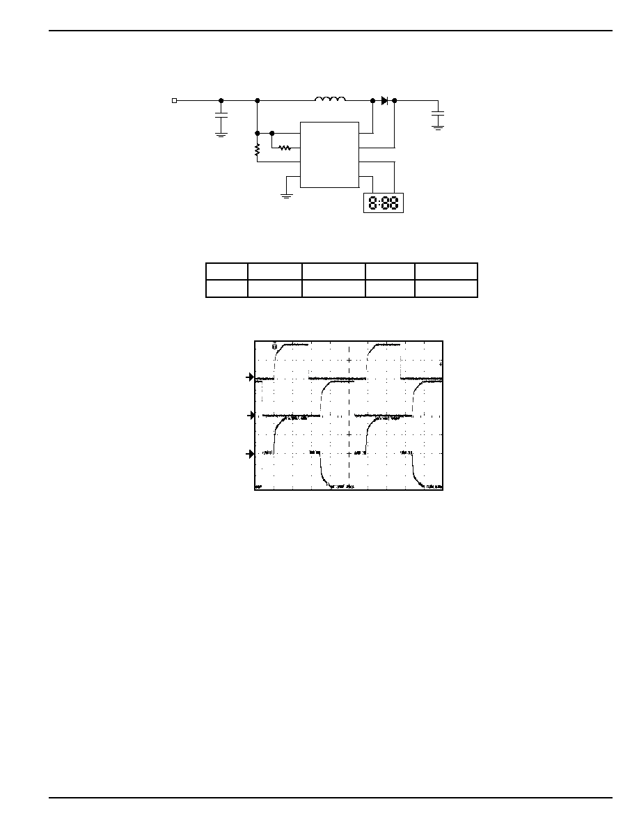
Pre-designed Application Circuit
R1
332k
R2
3.32M
Li-Ion Battery
V
IN
3.0V to 4.2V
C1
0.22
µ
F/10V
Murata
GRM39X7R 224K10
C
OUT
0.01
µ
F/100V
GRM40X7R103K
D1
Vishay Telefunken
MCL4148
L1
220
µ
H
Murata
LQH4C221K04
1
5
6
8
7
2
3
4
SW
CS
VA
VB
VDD
RSW
REL
GND
MIC4827
3in
2
LAMP
C2
10
µ
F/6.3V
Murata
GRM42-6X5R106K6.3
V
IN
I
IN
V
A
V
B
F
EL
Lamp Size
3.3V
28mA
180V
PP
106Hz
3 in
2
TIME (2ms/div)
V
B
(50V/div)
V
A
(50V/div)
V
A
--
V
B
(50V/div)
Figure 5. Typical 100Hz EL Driver for 3in
2
Lamp
Application Information
Inductor
In general, smaller value inductors, which can handle more
current, are more suitable to drive larger size lamps. As the
inductor value decreases, the switching frequency (con-
trolled by R
SW
) should be increased to avoid saturation or the
input voltage should be increased. Typically, inductor values
ranging from 220
µ
H to 560
µ
H can be used. Murata offers the
LQH3C series up to 560
µ
H and LQH4C series up to 470
µ
H,
with low DC resistance. A 220
µ
H Murata (LQH4C221K04)
inductor is recommended for driving a lamp size of 3 square
inches. It has a maximum DC resistance of 4.0
.
Diode
The application circuit specifies the 1N4148 or equivalent. It
has a forward current of 150mA and a typical forward voltage
of 950mV. For applications that are not cost driven, a fast-
switching diode with lower forward voltage and higher re-
verse voltage can be used to enhance the efficiency, such as
BAV20WS or BAS20W.
Output Capacitor
Low ESR capacitors should be used at the regulated boost
output (CS pin) of the MIC4827 to minimize the switching
output ripple voltage. Selection of the capacitor value will
depend upon the peak inductor current, inductor size, and the
load. MuRata offers the GRM42-6 series with up to 0.047
µ
F
at 100V, with a X7R temperature coefficient in 1206 surface-
mount package. Typically, values ranging from 0.01
µ
F to
0.1
µ
F at 100V can be used for the regulated boost output
capacitor.
September 2001
9
MIC4827
MIC4827
Micrel
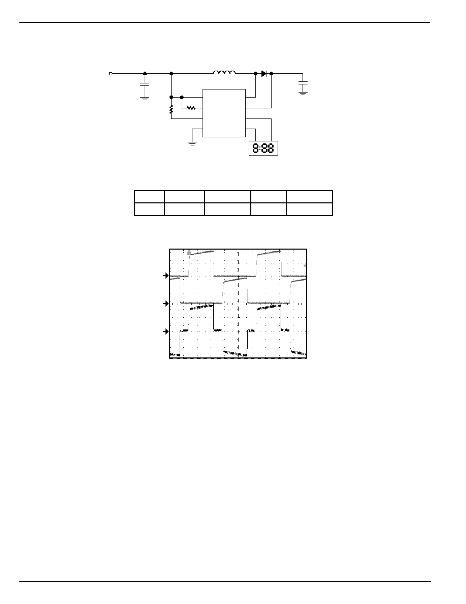
V
IN
I
IN
V
A
V
B
F
EL
Lamp Size
3.3V
18mA
180V
PP
104Hz
2in
2
R1
332k
R2
3.32M
V
IN
2.4V to 5.5V
C
OUT
0.033
µ
F/100V
GRM42-6X7R333K100
D1
Diodes
BAS20W
L1
220
µ
H
Murata
LQH4C221K04
1
5
6
8
7
2
3
4
SW
CS
VA
VB
VDD
RSW
REL
GND
MIC4827
EL LAMP
LSI
X533-13
C2
10
µ
F/6.3V
Murata
GRM42-6X5R106K6.3
TIME (2ms/div)
V
B
(50V/div)
V
A
(50V/div)
V
A
--
V
B
(50V/div)
Figure 6. Typical EL Driver for 2in
2
Lamp with C
S
= 0.033
µ
F
MIC4827
Micrel
MIC4827
10
September 2001
V
IN
I
IN
V
A
V
B
F
EL
Lamp Size
3.3V
21mA
180V
PP
102Hz
2in
2
R1
562k
R2
3.32M
V
IN
3.3V to 5.5V
C
OUT
0.033
µ
F/100V
GRM42-2X7R104K100
D1
Diodes
BAS20W
L1
560k
Murata
LQ32CN561K21
1
5
6
8
7
2
3
4
SW
CS
VA
VB
VDD
RSW
REL
GND
MIC4827
EL LAMP
LSI
X533-13
C2
10
µ
F/6.3V
Murata
GRM42-6X5R106K6.3
TIME (2ms/div)
V
B
(50V/div)
V
A
(50V/div)
V
A
--
V
B
(50V/div)
Figure 7. Typical EL Driver for 2in
2
Lamp with 560
µ
H inductor
September 2001
11
MIC4827
MIC4827
Micrel
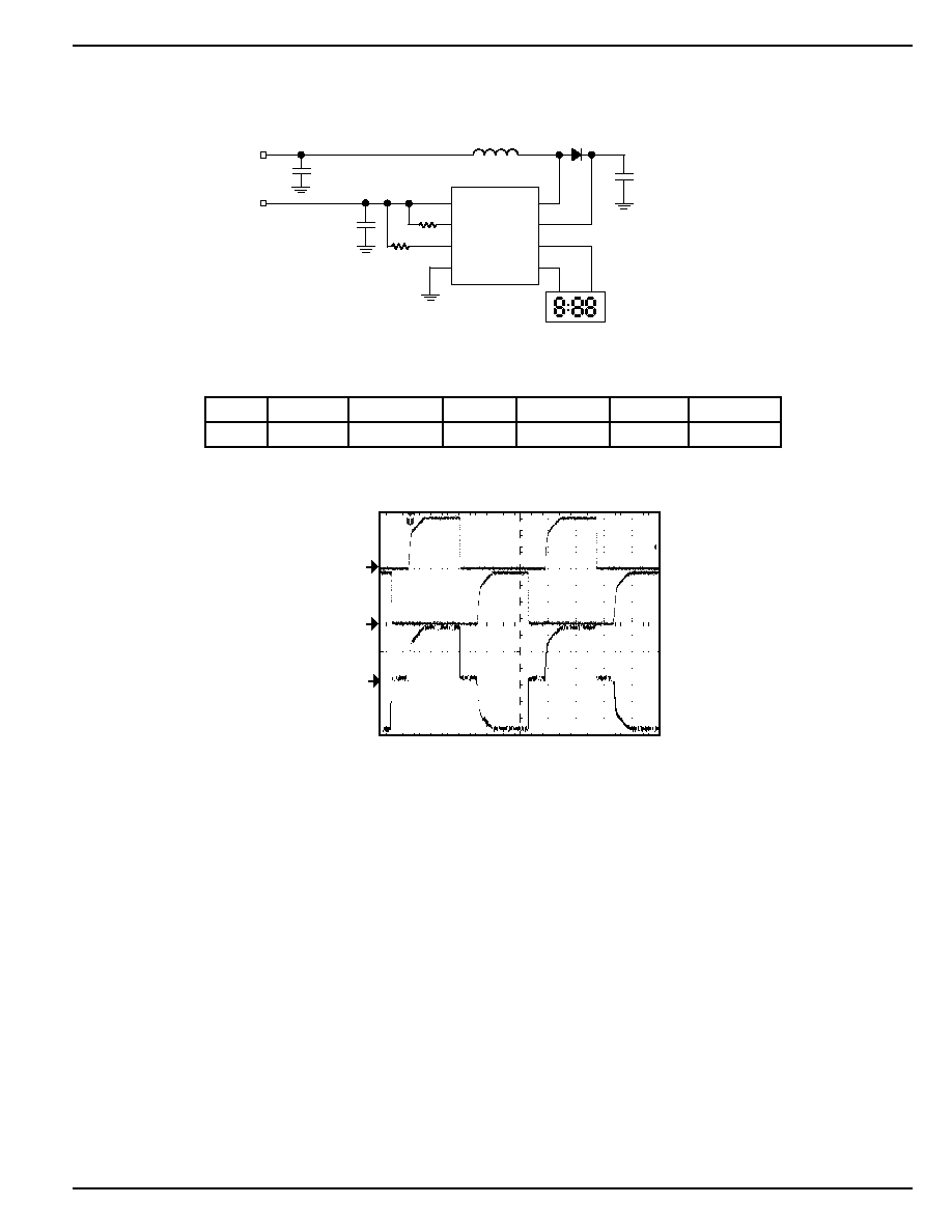
R1
562k
R2
3.32M
V
IN
1.5V
C
OUT
0.01
µ
F/100V
GRM42-2X7R104K100
D1
Diodes
BAS20W
L1
220
µ
H
Murata
LQH4C221K04
1
5
6
8
7
2
3
4
SW
CS
VA
VB
VDD
RSW
REL
GND
MIC4827
EL LAMP
C2
10
µ
F/6.3V
Murata
GRM42-6X5R106K6.3
V
DD
1.8V to 5.5V
C1
0.01
µ
F/50V
Murata
GRM42-6X5R106K6.3
TIME (2ms/div)
V
B
(50V/div)
V
A
(50V/div)
V
A
--
V
B
(50V/div)
Figure 8. Typical Split Power Supplies Applications
V
IN
I
IN
V
DD
I
DD
V
A
V
B
F
EL
Lamp Size
1.5V
26mA
3.0V
32
µ
A
180V
PP
104Hz
1.6in
2
MIC4827
Micrel
MIC4827
12
September 2001
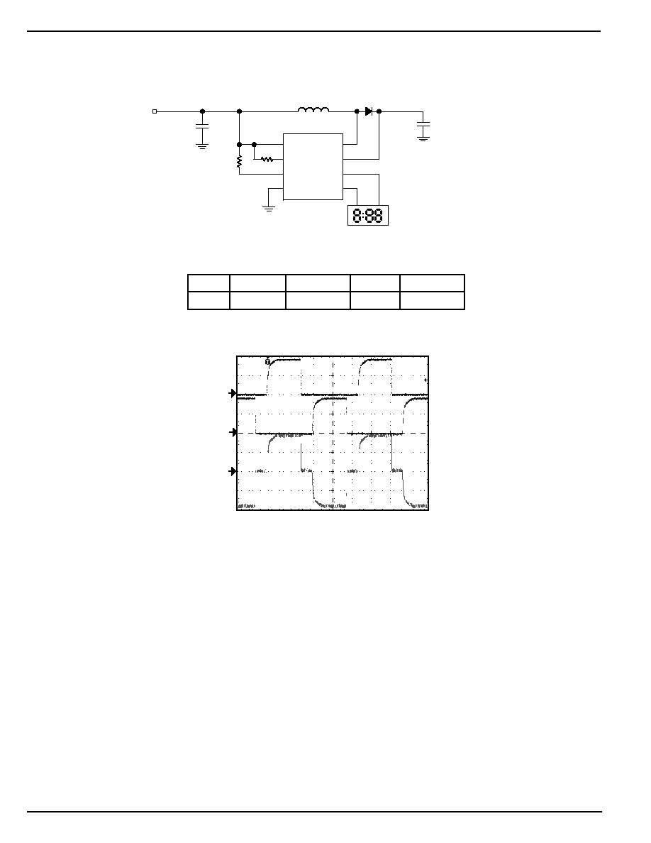
V
IN
I
IN
V
A
V
B
F
EL
Lamp Size
3.0V
31mA
180V
PP
104Hz
5.3in
2
R1
1M
R2
3.32M
V
IN
1.8V to 3.3V
(2X Alkaline Batteries)
C
OUT
0.1
µ
F/100V
GRM42-2X7R104K100
D1
Diodes
BAS20W
L1
220
µ
H
Murata
LQ32CN561K21
1
5
6
8
7
2
3
4
SW
CS
VA
VB
VDD
RSW
REL
GND
MIC4827
EL LAMP
Elite
12607-N
C2
10
µ
F/6.3V
Murata
GRM42-6X5R106K6.3
TIME (2ms/div)
V
B
(50V/div)
V
A
(50V/div)
V
A
--
V
B
(50V/div)
Figure 9. Typical EL Driver for Remote Control Lamp
(Blue Phosphor) Applications
September 2001
13
MIC4827
MIC4827
Micrel
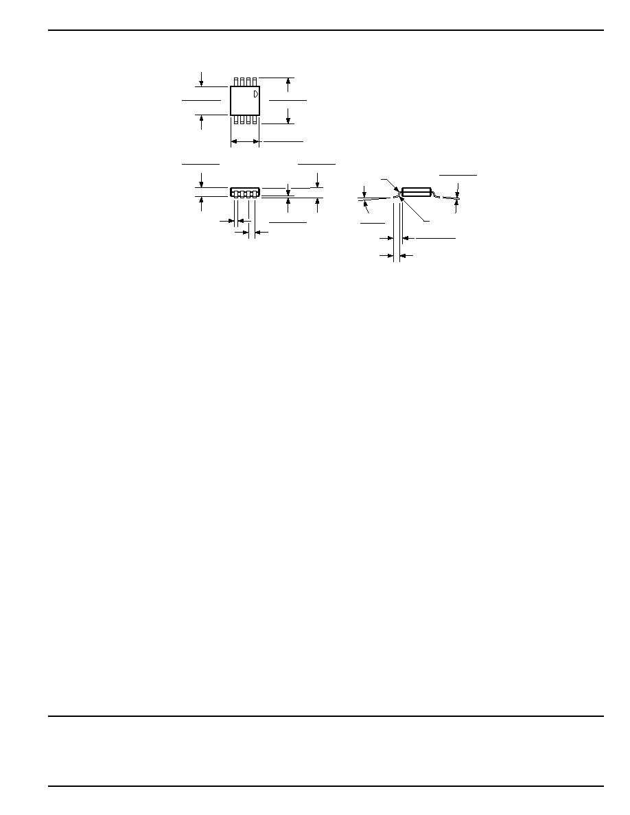
Package Information
0.008 (0.20)
0.004 (0.10)
0.039 (0.99)
0.035 (0.89)
0.021 (0.53)
0.012 (0.03) R
0.0256 (0.65) TYP
0.012 (0.30) R
5
°
MAX
0
°
MIN
0.122 (3.10)
0.112 (2.84)
0.120 (3.05)
0.116 (2.95)
0.012 (0.3)
0.007 (0.18)
0.005 (0.13)
0.043 (1.09)
0.038 (0.97)
0.036 (0.90)
0.032 (0.81)
DIMENSIONS:
INCH (MM)
0.199 (5.05)
0.187 (4.74)
8-Lead MSOP (MM)
MICREL INC.
1849 FORTUNE DRIVE
SAN JOSE, CA 95131
USA
TEL
+ 1 (408) 944-0800
FAX
+ 1 (408) 944-0970
WEB
http://www.micrel.com
This information is believed to be accurate and reliable, however no responsibility is assumed by Micrel for its use nor for any infringement of patents or
other rights of third parties resulting from its use. No license is granted by implication or otherwise under any patent or patent right of Micrel Inc.
© 2001 Micrel Incorporated