SDB101
THRU
SDB107
1 Amp Single Phase
Glass Passivated
Bridge Rectifier
50 to 1000 Volts
Features
·
Surface Mount Package
·
Glass Passivated Diode Construction
·
Moisture Resistant Epoxy Case
·
High Surge Current Capability
Maximum Ratings
·
Operating Temperature: -55
°
C to +150
°
C
·
Storage Temperature: -55
°
C to +150
°
C
MCC
Catalog
Number
Device
Marking
Maximum
Recurrent
Peak Reverse
Voltage
Maximum
RMS
Voltage
Maximum
DC
Blocking
Voltage
SDB101 --- 50V 35V 50V
SDB102 --- 100V 70V 100V
SDB103 --- 200V 140V 200V
SDB104 --- 400V 280V 400V
SDB105 --- 600V 420V 600V
SDB106 --- 800V 560V 800V
SDB107 --- 1000V 700V 1000V
Electrical Characteristics @ 25
°
C Unless Otherwise Specified
Average Forward
Current
I
F(AV)
1 A T
A
= 40
°
C
Peak Forward Surge
Current
I
FSM
50A 8.3ms, half sine
Maximum
Instantaneous
Forward Voltage
V
F
1.1V I
FM
= 1.0A;
T
A
= 25
°
C
Maximum DC
Reverse Current At
Rated DC Blocking
Voltage
I
R
10
µ
A
0.5mA
T
A
= 25
°
C
T
A
= 125
°
C
Maximum Reverse
Recovery Time
T
rr
36ns I
F
=0.5A, I
R
=1.0A,
I
rr
=0.25A
Typical Junction
Capacitance
C
J
25pF Measured at
1.0MHz, V
R
=4.0V
*Pulse Test: Pulse Width 300
µ
sec, Duty Cycle 1%
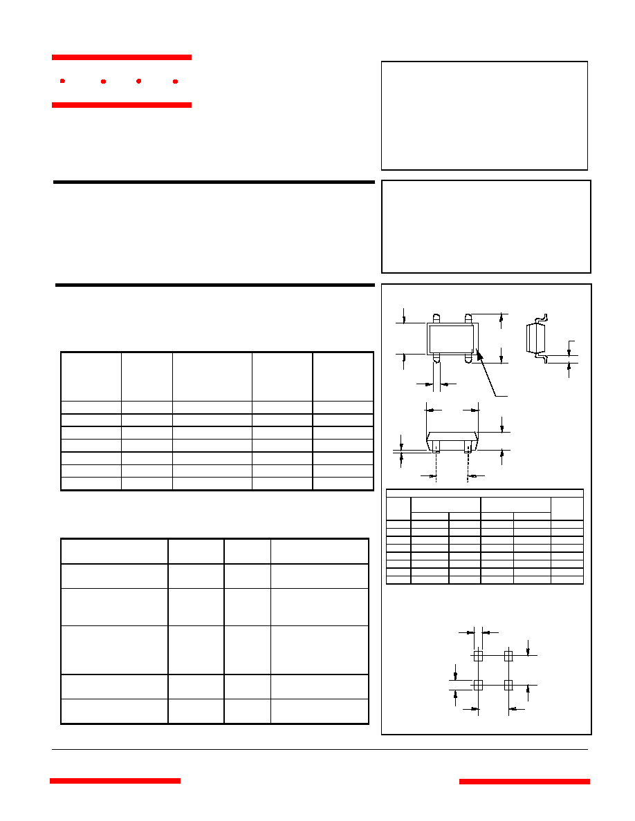
SDB-1
Suggested Solder Pad
Layout
DIMENSIONS
INCHES MM
DIM MIN MAX MIN MAX NOTE
C .040 .060 1.02 1.52
A .320 .335 8.13 8.50
B .245 .255 6.20 6.50
E .120 .130 3.05 3.30
D .386 .404 9.80 10.3
G .002 .008 0.05 0.20
H .195 .205 5.00 5.20
K .040 .047 1.02 1.20 TYP
.047"
.060"
.205"
.344"
omponents
21201 Itasca Street Chatsworth
!"#
$
% !"#
M C C
B
C
D
A
E
G
H
K
Notch in Case
+
-
www.
mccsemi
.com
Version: 3 2003/01/08
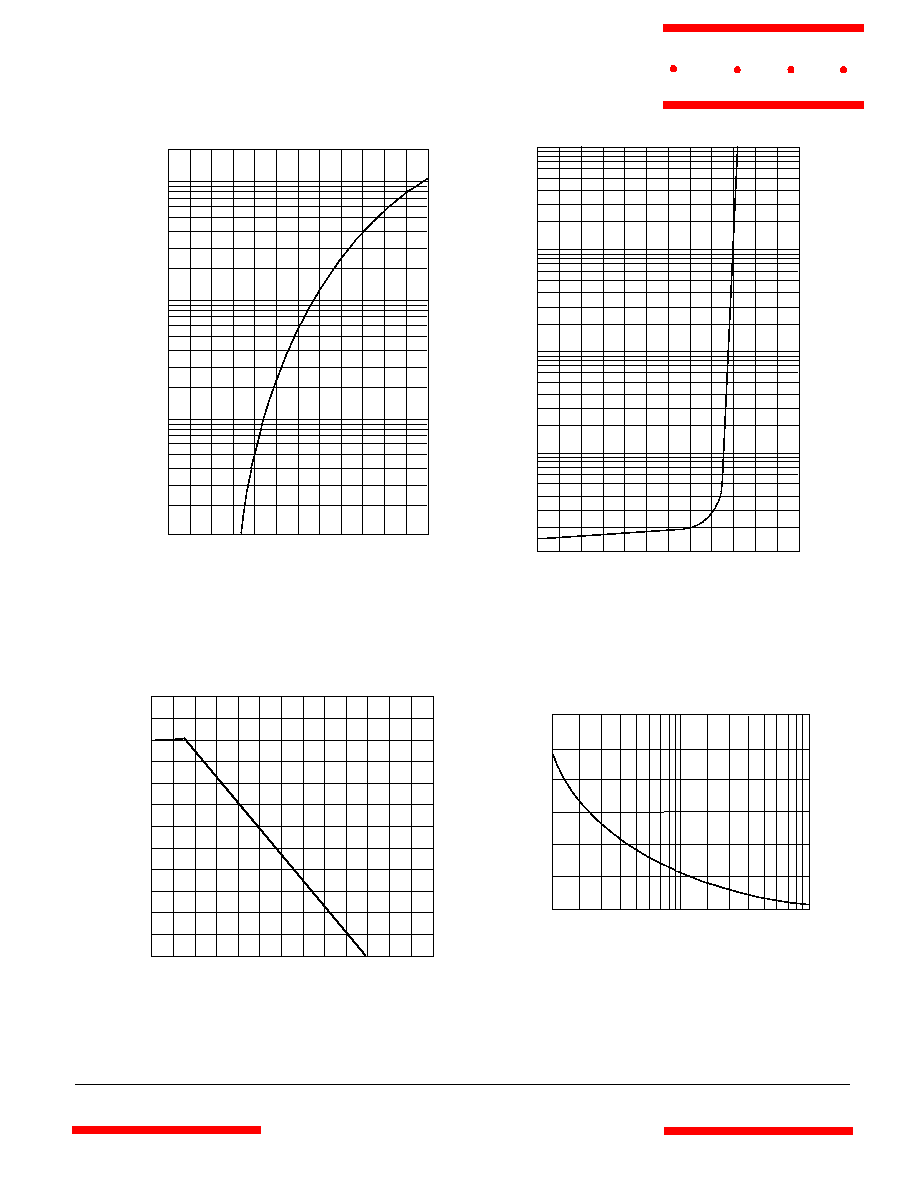
SDB101 thru SDB107
Instantaneous Reverse Leakage Current - MicroAmperes
versus
Percent Of Rated Peak Reverse Voltage - Volts
Average Forward Rectified Current - Amperes
versus
Ambient Temperature -
°
C
Figure 3
Forward Derating Curve
0
175
50
75
100
125
0
.2
.4
.6
Single Phase, Half Wave
60Hz Resistive or Inductive Load
Amps
°
C
150
.8
1.0
1.2
Instantaneous Forward Current - Amperes
versus
Instantaneous Forward Voltage - Volts
Figure 1
Typical Forward Characteristics
4
6
20
10
Amps
1
100
4
0
10
5
20
30
8
Figure 4
Peak Forward Surge Current
Peak Forward Surge Current - Amperes
versus
Number Of Cycles At 60Hz - Cycles
Amps
Cycles
2
6
10 20
60 80
40
40
50
60
.4
.6
.8
1.0
1.2
1.4
.01
.02
.04
.06
.1
.2
.4
.6
1
2
25
°
C
Volts
Figure 2
Typical Reverse Characteristics
Volts
4
6
20
10
µ
Amps
20
120
40
60
80
100
.01
.02
.04
.06
.1
.2
.4
.6
1
2
T
A
=25
°
C
40
60
100
140
M C C
www.
mccsemi
.com
Version: 3 2003/01/08