Äîêóìåíòàöèÿ è îïèñàíèÿ www.docs.chipfind.ru
General Description
The MAX5921/MAX5939 hot-swap controllers allow a cir-
cuit card to be safely hot plugged into a live backplane.
The MAX5921/MAX5939 operate from -20V to -80V and
are well suited for -48V power systems. These devices
are pin compatible with both the LT1640 and LT4250 and
provide improved features over these devices.
The MAX5921/MAX5939 provide a controlled turn-on to
circuit cards preventing damage to board connectors,
board components, and preventing glitches on the
power-supply rail. The MAX5921/MAX5939 provide
undervoltage, overvoltage, and overcurrent protection.
These devices ensure that the input voltage is stable
and within tolerance before applying power to the load.
Both the MAX5921 and MAX5939 protect a system
against overcurrent and short-circuit conditions by turn-
ing off the external MOSFET in the event of a fault con-
dition. The MAX5921/MAX5939 protect against input
voltage steps by limiting the load current to a safe level
without turning off power to the load.
The device features an open-drain power-good status
output, PWRGD or PWRGD for enabling downstream
converters (see Selector Guide). A built-in thermal shut-
down feature is also included to protect the external
MOSFET in case of overheating. The MAX5939 features
a latched fault output. The MAX5921 contains built-in
autoretry circuitry after a fault condition.
The MAX5921/MAX5939 are available in an 8-pin SO
package and operate in the extended -40°C to +85°C
temperature range.
Applications
Telecom Line Cards
Network Switches/Routers
Central-Office Line Cards
Server Line Cards
Base-Station Line Cards
Features
o Allows Safe Board Insertion and Removal
from a Live -48V Backplane
o Pin-Compatible with LT1640 and LT4250
o Circuit Breaker Immunity to Input Voltage Steps
and Current Spikes
o 450mA GATE Pulldown Current During Short-
Circuit Condition
o Exponential GATE Pulldown Current
o Withstands -100V Input Transients with No
External Components
o Programmable Inrush and Short-Circuit Current
Limits
o Operates from -20V to -80V
o Programmable Overvoltage Protection
o Programmable Undervoltage Lockout
with Built-In Glitch Filter
o Overcurrent Fault Integrator
o Powers Up into a Shorted Load
o Power-Good Control Output
o Thermal Shutdown Protects External MOSFET
MAX5921/MAX5939
-48V Hot-Swap Controllers with External
R
SENSE
and High Gate Pulldown Current
________________________________________________________________ Maxim Integrated Products
1
GATE
SENSE
V
EE
1
2
8
7
V
DD
DRAIN
OV
UV
PWRGD
(PWRGD)
SO
TOP VIEW
3
4
6
5
MAX5921
MAX5939
() FOR MAX5921B/F AND MAX5939B/F.
Pin Configuration
Ordering Information
19-2946; Rev 0; 9/03
For pricing, delivery, and ordering information, please contact Maxim/Dallas Direct! at
1-888-629-4642, or visit Maxim's website at www.maxim-ic.com.
PART
TEMP RANGE
PIN-PACKAGE
MAX5921AESA
-40°C to +85°C
8 SO
MAX5921BESA
-40°C to +85°C
8 SO
Typical Operating Circuit and Selector Guide appear at end
of data sheet.
Ordering Information continued at end of data sheet.
MAX5921/MAX5939
-48V Hot-Swap Controllers with External
R
SENSE
and High Gate Pulldown Current
2
_______________________________________________________________________________________
ABSOLUTE MAXIMUM RATINGS
ELECTRICAL CHARACTERISTICS
(V
EE
= 0V, V
DD
= 48V, T
A
= -40°C to +85°C, unless otherwise noted. Typical values are at T
A
= +25°C, unless otherwise noted.) (Notes 1, 4)
Stresses beyond those listed under "Absolute Maximum Ratings" may cause permanent damage to the device. These are stress ratings only, and functional
operation of the device at these or any other conditions beyond those indicated in the operational sections of the specifications is not implied. Exposure to
absolute maximum rating conditions for extended periods may affect device reliability.
All Voltages Are Referenced to VEE, Unless Otherwise Noted
Supply Voltage (VDD - VEE )................................-0.3V to +100V
DRAIN, PWRGD, PWRGD ....................................-0.3V to +100V
PWRGD to DRAIN ................................................ -0.3V to +95V
PWRGD to VDD .......................................................-95V to +85V
SENSE (Internally Clamped) .................................-0.3V to +1.0V
GATE (Internally Clamped) ....................................-0.3V to +18V
UV and OV..............................................................-0.3V to +60V
Current into SENSE...........................................................+40mA
Current into GATE...........................................................+300mA
Current into Any Other Pin................................................+20mA
Continuous Power Dissipation (TA = +70°C)
8-Pin SO (derate 5.9mW/°C above +70°C)..................471mW
Operating Temperature Range ...........................-40°C to +85°C
Junction Temperature .....................................................+150°C
Storage Temperature Range .............................-65°C to +150°C
Lead Temperature (soldering, 10s) .................................+300°C
PARAMETER
SYMBOL
CONDITIONS
MIN
TYP
MAX
UNITS
POWER SUPPLIES
Operating Input Voltage Range
V
DD
20
80
V
Supply Current
I
DD
Current into V
DD
with UV = 3V, OV, DRAIN,
SENSE = V
EE
, GATE = floating
0.7
2
mA
GATE DRIVER AND CLAMPING CIRCUITS
Gate Pullup Current
I
PU
GATE drive on, V
GATE
= V
EE
-30
-45
-60
µA
Gate Pulldown Current
I
PD
V
SENSE
- V
EE
= 100mV, V
GATE
= 2V (Note 2)
24
50
70
mA
External Gate Drive
V
GATE
V
GATE
- V
EE
, steady state, 20V
V
DD
80V
10
13.5
18
V
GATE to V
EE
Clamp Voltage
V
GSCLMP
V
GATE
- V
EE
, I
GS
= 30mA
15
16.4
18
V
CIRCUIT BREAKER
Current-Limit Trip Voltage
V
CL
V
CL
= V
SENSE
- V
EE
40
50
60
mV
SENSE Input Current
I
SENSE
V
SENSE
= 50mV
-1
-0.2
0
µA
UNDERVOLTAGE LOCKOUT
Supply Internal Undervoltage
Lockout Voltage High
V
UVLOH
V
DD
increasing
13.8
15.4
17.0
V
Supply Internal Undervoltage
Lockout Voltage Low
V
UVLOL
V
DD
decreasing
11.8
13.4
15.0
V
UV INPUT
UV High Threshold
V
UVH
UV voltage increasing
1.240
1.255
1.270
V
UV Low Threshold
V
UVL
UV voltage decreasing
1.105
1.125
1.145
V
UV Hysteresis
V
UVHY
130
mV
UV Input Current
I
INUV
UV = V
EE
-0.5
0
µA
OV INPUT
OV High Threshold
V
OVH
OV voltage rising
1.235
1.255
1.275
V
OV Low Threshold
V
OVL
OV voltage decreasing
1.189
1.205
1.221
V
OV Voltage Reference Hysteresis
V
OVHY
50
mV
OV Input Current
I
INOV
OV = V
EE
-0.5
0
µA
MAX5921/MAX5939
-48V Hot-Swap Controllers with External
R
SENSE
and High Gate Pulldown Current
_______________________________________________________________________________________
3
ELECTRICAL CHARACTERISTICS (continued)
(V
EE
= 0V, V
DD
= 48V, T
A
= -40°C to +85°C, unless otherwise noted. Typical values are at T
A
= +25°C, unless otherwise noted.) (Notes 1, 4)
PARAMETER
SYMBOL
CONDITIONS
MIN
TYP
MAX
UNITS
PWRGD OUTPUT SIGNAL (REFERENCED TO DRAIN)
DRAIN Input Current
I
DRAIN
V
DRAIN
= 48V
10
80
250
µA
DRAIN Threshold for PWRGD
V
DL
V
DRAIN
- V
EE
threshold for power-good
condition, DRAIN decreasing
1.1
1.7
2.0
V
GATE High Threshold
V
GH
V
GATE
- V
GATE
, decreasing
1.0
1.6
2.0
V
V
PWRGD
= 80V, V
DRAIN
= 48V
10
PWRGD,
PWRGD Output
Leakage
I
OH
V
PWRGD
= 80V, V
DRAIN
= 0V
10
µA
PWRGD Low Voltage
(V
PWRGD
- V
EE
)
V
OL
V
DRAIN
- V
EE
< V
DL
, I
SINK
= 5mA
(A, E versions)
0.11
0.4
V
PWRGD Low Voltage
(V
PWRGD
- V
DRAIN
)
V
OL
V
DRAIN
= 5V, I
SINK
= 5mA (B, F versions)
0.11
0.4
V
OVERTEMPERATURE PROTECTION
Overtemperature Threshold
T
OT(TH)
Junction temperature, temperature rising
135
°C
Overtemperature Hysteresis
T
HYS
See Thermal Shutdown section
20
°C
AC PARAMETERS
OV High to GATE Low
t
PHLOV
Figures 1a, 2
0.5
µs
UV Low to GATE Low
t
PHLUV
Figures 1a, 3
0.4
µs
OV Low to GATE High
t
PLHOV
Figures 1a, 2
3.3
µs
UV High to GATE High
t
PLHUV
Figures 1a, 3
8.4
ms
SENSE High to GATE Low
t
PHLSENSE
Figures 1a, 4a
1
µs
A, B versions
0.35
0.5
0.65
Current Limit to GATE Low
t
PHLCL
Time from continuous
current limit to GATE
shutdown (see Overcurrent
Fault Integrator section),
Figures 1b, 4b
E, F versions
1.4
2.0
2.6
ms
Figures 1a, 5a; A and E versions
8.2
DRAIN Low to
PWRGD Low
DRAIN Low to (PWRGD - DRAIN)
High
t
PHLDL
Figures 1a, 5a; B and F versions
8.2
ms
Figures 1a, 5b; A and E versions
8.2
GATE High to
PWRGD Low
GATE High to (PWRGD - DRAIN)
High
t
PHLGH
Figures 1a, 5b; B and F versions
8.2
ms
TURN-OFF
Latch-Off Period
t
OFF
(Note 3)
A, B, E, F versions
128 x
t
PHLCL
ms
Note 1:
All currents into device pins are positive; all currents out of device pins are negative. All voltages are referenced to V
EE
,
unless otherwise specified.
Note 2:
Gate pulldown current after the current limit to GATE low (t
PHLCL
) time has elapsed.
Note 3:
Minimum duration of GATE pulldown following a circuit breaker fault. The MAX5921_ automatically restarts after a circuit
breaker fault. The MAX5939_ is latched off and can be reset by toggling UV low. The GATE pulldown does not release until
t
OFF
has elapsed.
Note 4:
The min/max limits are 100% production tested at +25°C and +85°C and guaranteed by design at -40°C.
MAX5921/MAX5939
-48V Hot-Swap Controllers with External
R
SENSE
and High Gate Pulldown Current
4
_______________________________________________________________________________________
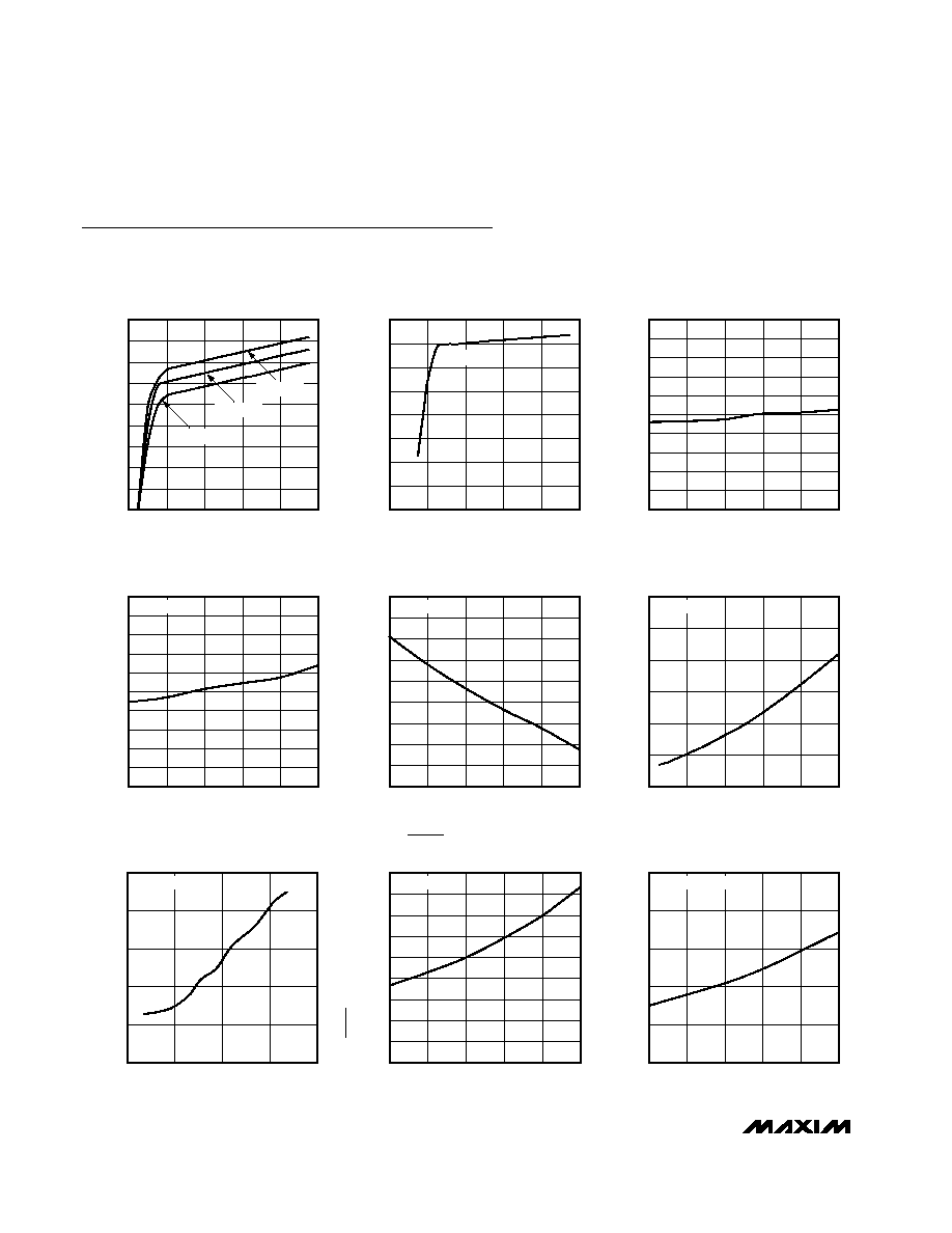
Typical Operating Characteristics
(V
DD
= +48V, V
EE
= 0V, T
A
= +25°C, unless otherwise noted.)
43.0
43.2
43.8
43.6
43.4
44.8
44.6
44.2
44.0
44.4
45.0
-40
10
-15
35
60
85
GATE PULLUP CURRENT
vs. TEMPERATURE
MAX5921TOC04
TEMPERATURE (
°C)
GATE PULLUP CURRENT (
µ
A)
V
GATE
= 0V
25
30
45
40
35
65
55
50
60
70
-40
10
-15
35
60
85
GATE PULLDOWN CURRENT
vs. TEMPERATURE AFTER A FAULT
MAX5921TOC05
TEMPERATURE (
°C)
GATE PULLDOWN CURRENT (mA)
V
GATE
= 2V
0
15
60
45
30
75
90
0
40
20
60
80
100
GATE PULLDOWN CURRENT
vs. OVERDRIVE DURING A CURRENT FAULT
MAX5921TOC06
OVERDRIVE (mV)
GATE PULLDOWN CURRENT (mA)
V
GATE
= 2V
0
100
400
300
200
500
600
900
750
1050
1200
GATE PULLDOWN CURRENT
vs. OVERDRIVE DURING A SHORT CIRCUIT
MAX5921TOC07
OVERDRIVE (mV)
GATE PULLDOWN CURRENT (mV)
V
GATE
= 2V
0
40
160
120
80
20
140
100
60
180
-40
10
-15
35
60
85
PWRGD OUTPUT LOW VOLTAGE
vs. TEMPERATURE (MAX5921A)
MAX5921TOC08
TEMPERATURE (
°C)
PWRGD OUTPUT LOW VOLTAGE (mV)
I
OUT
= 5mA
0.001
0.01
10
1
0.1
100
-40
10
-15
35
60
85
PWRGD OUTPUT LEAKAGE CURRENT
vs. TEMPERATURE (MAX5921B)
MAX5921TOC09
TEMPERATURE (
°C)
PWRGD OUTPUT LEAKAGE CURRENT (nA)
V
DRAIN
- V
EE
> 2.4V
0
200
100
500
400
300
800
700
600
900
0
40
20
60
80
100
SUPPLY CURRENT
vs. SUPPLY VOLTAGE
MAX5921TOC01
SUPPLY VOLTAGE (V)
SUPPLY CURRENT (
µ
A)
T
A
= +85
°C
T
A
= +25
°C
T
A
= -40
°C
7
9
8
12
11
10
14
13
15
0
40
20
60
80
100
GATE VOLTAGE
vs. SUPPLY VOLTAGE
MAX5921TOC02
SUPPLY VOLTAGE (V)
GATE VOLTAGE (V)
T
A
= +25
°C
40
42
48
46
44
58
56
52
50
54
60
-40
10
-15
35
60
85
CURRENT-LIMIT TRIP VOLTAGE
vs. TEMPERATURE
MAX5921TOC03
TEMPERATURE (
°C)
TRIP VOLTAGE (mV)
MAX5921/MAX5939
-48V Hot-Swap Controllers with External
R
SENSE
and High Gate Pulldown Current
_______________________________________________________________________________________
5
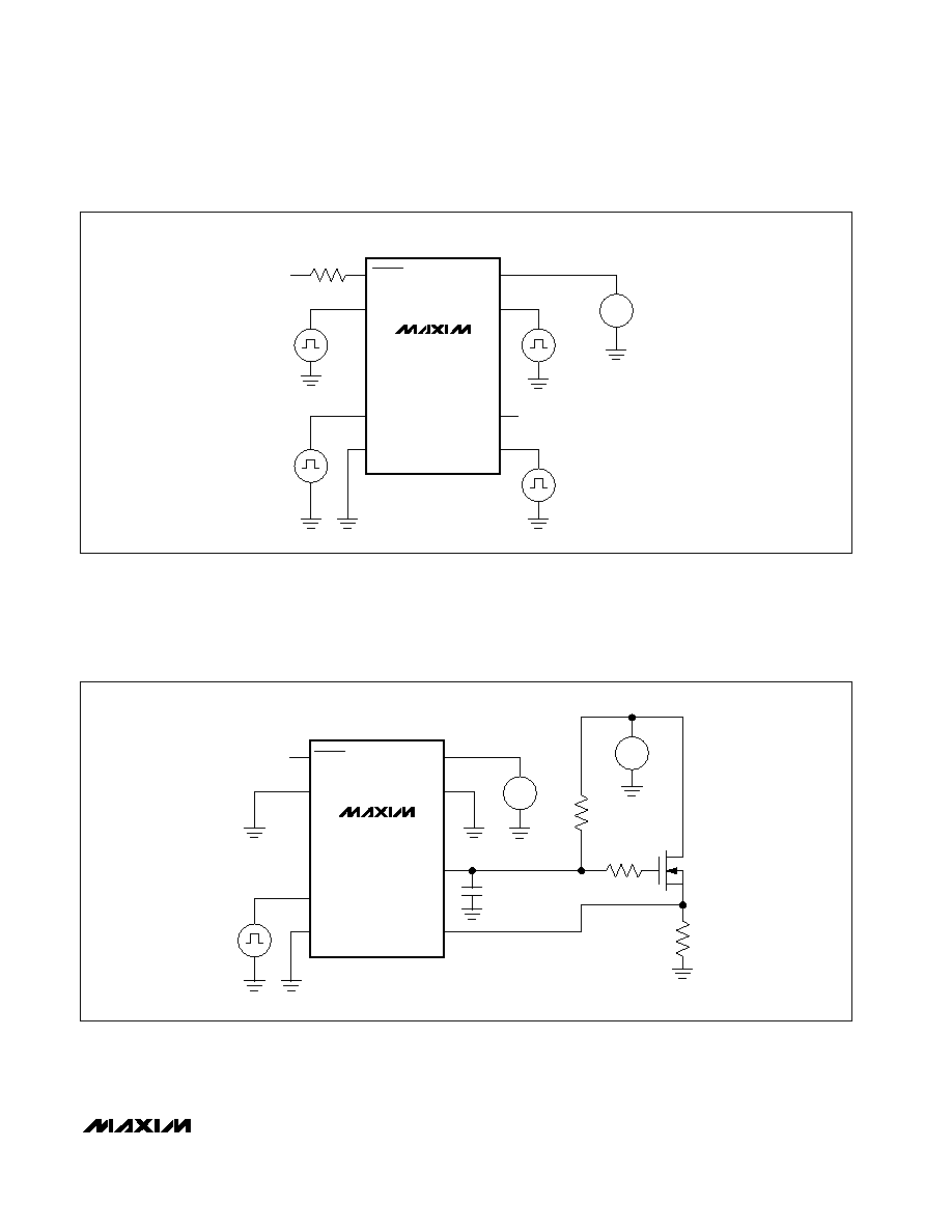
MAX5921
MAX5939
PWRGD/PWRGD
OV
UV
V
EE
V
DD
DRAIN
GATE
SENSE
R
5k
V+
5V
V
OV
V
UV
V
SENSE
V
DRAIN
V
S
+
-
+48V
Figure 1a. Test Circuit 1
MAX5921
MAX5939
OV
UV
V
EE
V
DD
DRAIN
GATE
SENSE
V
UV
V
S
+
-
+48V
V
S
+
-
+20V
10k
10
IRF530
0.1
µF
PWRGD/PWRGD
Figure 1b. Test Circuit 2