
General Description
The MAX5427 evaluation kit (EV kit) is a fully assembled
and tested surface-mount circuit board that evaluates
the MAX5427 digital potentiometer. Included software
generates the required signals for one-time-programma-
ble operation and allows easy control of the wiper posi-
tion. An on-board 8-pin µMAX socket eases replacement
of the device. The EV kit is designed to be connected to
a standard IBM-compatible PC-parallel (printer) port.
Windows
®
95/98/2000-compatible software provides a
user-friendly interface to exercise the MAX5427's fea-
tures. The program is menu driven and offers a graphic
user interface with control buttons. (Note: Windows 2000
requires the installation of a driver; refer to Win2000.pdf
or Win2000.txt located on the diskette for information.)
This EV kit can also be used to evaluate the MAX5428
and MAX5429 digital potentiometers.
Windows is a registered trademark of Microsoft Corp.
Features
o On-Board 8-Pin µMAX Socket
o Windows 95/98/2000 Evaluation Software
o Software Adjusts and Programs Wiper Position
o Fully Assembled and Tested
Evaluates: MAX5427/MAX5428/MAX5429
MAX5427 Evaluation Kit
________________________________________________________________ Maxim Integrated Products
1
For pricing, delivery, and ordering information, please contact Maxim/Dallas Direct! at
1-888-629-4642,or visit Maxim's website at www.maxim-ic.com.
19-2475; Rev 0; 5/02
Ordering Information
Component List
PART
TEMP RANGE
IC PACKAGE
MAX5427EVKIT
0°C to +70°C
8 µMAX
DESIGNATION
QTY
DESCRIPTION
C1
1
4.7µF ±20%, X5R 6.3V
ceramic capacitor (0805)
TDK C2012X5R0J475M
C2
1
22µF ±20%, X5R 16V ceramic
capacitor (1812)
TDK C4532X7R1C226M
D1
1
Green surface-mount LED
D2
1
Dual Shottky diode (SOT23)
Diodes INC BAT54C or
Fairchild BAT54C or
General Semiconductor or
BAT54C
J1
1
DB-25 right-angle plug (male)
R1
1
1.6k
±5% resistor (1206)
U1
1
8-pin µMAX socket
Wells-CTI 656-1082211
DESIGNATION
QTY
DESCRIPTION
U1
1
Digital potentiometer
(8-pin µMAX)
MAX5427EUA
U2
1
Low-voltage, analog switch (6-
pin SOT23)
MAX4544EUT
U3
1
Low-voltage level translator
(10-pin µMAX)
MAX1840EUB
None
1
MAX5427 PC board
None
1
3 1/2in software disk
MAX5427 evaluation kit
None
1
MAX5427 data sheet
None
1
MAX5427 EV kit data sheet
Note: To evaluate the MAX5428 or the MAX5429, request a
free sample of MAX5428EUA or MAX5429EUA with the
MAX5427EVKIT.

Evaluates: MAX5427/MAX5428/MAX5429
MAX5427 Evaluation Kit
2
_______________________________________________________________________________________
Quick Start
Recommended Equipment
· One variable DC power supply capable of supply-
ing between 2.7V and 5.5V at 100mA
· One fixed DC power supply capable of supplying
11V at 20mA
· One
ohmmeter
· A parallel printer port (this is a 25-pin socket on the
back of the computer)
· A computer running Windows 95, 98, or 2000.
(Note: Windows 2000 requires the installation of a
driver; refer to Win2000.pdf or Win2000.txt located
on the diskette for information.)
· A standard 25-pin, straight-through, male-to-female
cable (printer extension cable) to connect the com-
puter's parallel port to the MAX5427EVKIT
Procedure
The MAX5427 EV kit is fully assembled and tested. Follow
the steps below to verify board operation. Do not turn on
the power supply until all connections are completed:
1) Connect a cable from the computer's parallel port
to the MAX5427EVKIT. To avoid damaging the EV
kit or your computer, do not use a 25-pin SCSI port
or any other connector that is physically similar to
the 25-pin parallel printer port. The parallel port is
typically labeled LPT or PRINTER.
2) Adjust the variable power supply to 5V.
3) Ensure that the variable power supply is turned off.
4) Ensure that the fixed 11V power supply is turned
off.
5) Connect the positive terminal of the variable power
supply to the pad labeled VDD.
6) Connect the ground return of the variable power
supply to the corresponding pad labeled GND.
7) Connect the positive terminal of the fixed 11V power
supply to the pad labeled VPP.
8) Connect the ground return of the fixed 11V power
supply to the corresponding pad labeled GND.
9) Connect the positive terminal of the ohmmeter to
the pad marked H.
10) Connect the ground return of the ohmmeter to the
pad marked W.
11) Install the software by running the INSTALL.EXE
program. The install program copies the files and
creates icons for them in the Windows 95/98/2000
Start menu.
12) Turn on the 5V variable power supply.
13) Turn on the 11V fixed power supply.
14) Start the MAX5427 program by opening its icon in
the Start menu.
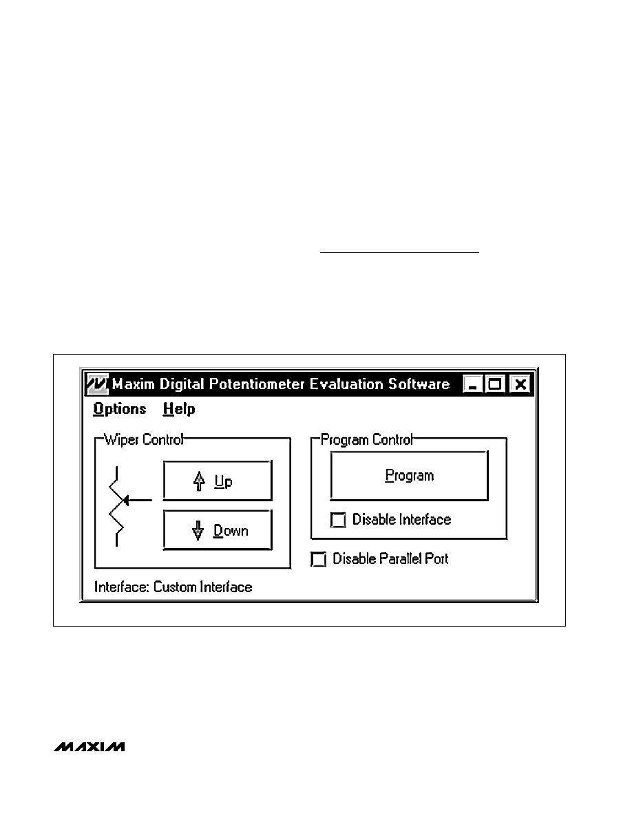
15) Wait until the program automatically detects the
MAX5427 and displays the main window (Figure 1).
The MAX5427 is now in its default power-on-reset
(POR) mode (wiper is at midscale for an unpro-
grammed device).
Detailed Description
of Software
Use the mouse or press the Tab key to navigate with the
arrow keys. Each of the buttons corresponds to com-
mands used to set the wiper position or program the
device. Note: Words in boldface indicate user-selectable
features in the software.
Wiper Control
The wiper position is adjusted sequentially through the
tap positions using a simple 2-wire interface. To incre-
ment the wiper position, press the Up button. To decre-
ment the wiper position, press the Down button.
SUPPLIER
PHONE
FAX
WEBSITE
Diodes Inc.
805-446-4800
805-446-4850
www.diodes.com
Fairchild Semiconductor
888-522-5372
N/A
www.fairchildsemi.com
General Semiconductor
760-804-9258
760-804-9259
www.gensemi.com
TDK
847-803-6100
847-390-4405
www.component.tdk.com
Wells-CTI
623-581-5330
623-780-3987
www.wellscti.com
Component Suppliers
Note: Please indicate that you are using the MAX5427 when contacting these component suppliers.
Evaluates: MAX5427/MAX5428/MAX5429
MAX5427 Evaluation Kit
_______________________________________________________________________________________
3
Program Control
To set the power-on position of the wiper, press the
Program button. Checking the Disable Interface
checkbox disables the 2-wire interface, preventing fur-
ther unwanted adjustment. Refer to the One-Time
Programming section of the MAX5427/MAX5428/
MAX5429 data sheet for more details.
Resetting the MAX5427
The Disable Parallel Port checkbox is used to reset
the digital potentiometer at power-up. Checking this
box forces all of the parallel port lines to a logic low
(0V), ensuring that the device is not powered through
the interface. To reset the device, do the following:
1) Turn off the power supply connected to VPP.
2) Turn off the power supply connected to VDD.
3) Check the Disable Parallel Port checkbox.
4) Disconnect any power supply connected to the H,
W, and L pads.
5) Turn on the power supply connected to VDD.
6) Turn on the power supply connected to VPP.
7) Uncheck the Disable Parallel Port checkbox.
Detailed Description
of Hardware
The MAX5427 EV kit is a complete programming plat-
form for the MAX5427 digital potentiometer. Parallel
port signals are level translated through a MAX1840 to
ensure reliable operation. The EV kit also includes an
8-pin µMAX socket to ease the programming of multiple
devices.
Figure 1. MAX5427 EV Kit Software Main Window
NOTE: THE MAIN WINDOW OF THE MAX5427 EV KIT SOFTWARE ALLOWS THE USER TO EASILY ADJUST AND PROGRAM THE MAX5427.
Evaluates: MAX5427/MAX5428/MAX5429
MAX5427 Evaluation Kit
4
_______________________________________________________________________________________
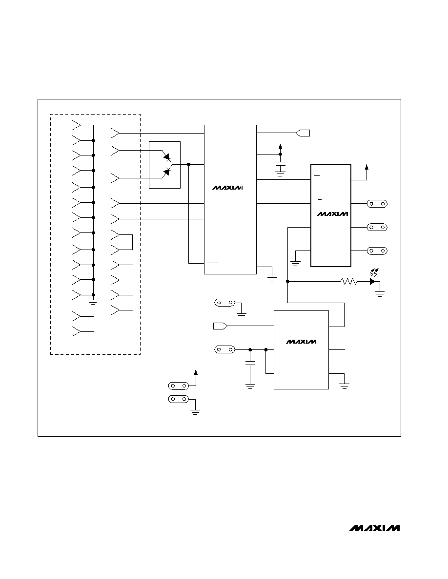
Figure 2. MAX5427 EV Kit Schematic
U3
MAX1840
U1
MAX5427
DATA
I/O
1
10
V
CC
C1
4.7
µF
9
CLK
8
RST
7
GND
6
IN
2
3
4
5
N.C.
N.C.
N.C.
N.C.
DV
CC
L
D2
R
CS
2
U/D
H
V
DD
VDD
VDD
H
6
8
3
V
PP
5
GND
4
1
2
6
C2
22
µF
VDD
IN
J1-4
CIN
J1-5
RIN
J1-13
J1-8
J1-2
J1-3
J1-1
J1-9
J114
J1-10
J1-11
J1-12
J1-15
J1-18
J1-19
J1-20
J1-21
J1-22
J1-23
J1-24
J1-25
N.C.
N.C.
J117
J116
SHDN
J1-6
J1-7
VPP
GND
GND
VDD
W
W
1
L
L
7
3
4
5
U2
MAX4544
IN
COM
V+
NO
NOTE: U1 IS A SOCKETED 8-PIN
µMAX.
WELLS-CTI PART NO. 656-1082211.
CONNECTOR DB-25
NC
GND
D1
R1
1.6k
Maxim cannot assume responsibility for use of any circuitry other than circuitry entirely embodied in a Maxim product. No circuit patent licenses are
implied. Maxim reserves the right to change the circuitry and specifications without notice at any time.
Maxim Integrated Products, 120 San Gabriel Drive, Sunnyvale, CA 94086 408-737-7600 _____________________ 5
© 2002 Maxim Integrated Products
Printed USA
is a registered trademark of Maxim Integrated Products.
Evaluates: MAX5427/MAX5428/MAX5429
MAX5427 Evaluation Kit
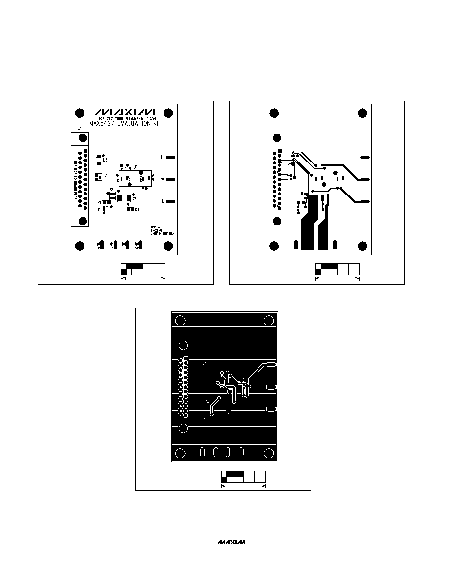
1.0"
Figure 3. MAX5427 EV Kit Component Placement Guide--
Component Side
1.0"
Figure 4. MAX5427 EV Kit PC Board Layout--Component Side
Figure 5. MAX5427 EV Kit PC Board Layout--Solder Side
1.0"