
_______________General Description
The MAX3238 true RS-232 transceiver achieves a
1µA supply current with Maxim's revolutionary
AutoShutdown Plus feature. When the device does not
sense a valid signal transition on either the receiver or
transmitter inputs within 30sec, the on-board power
supply and drivers shut down. This occurs if the RS-232
cable is disconnected or if the transmitters of the con-
nected peripheral are inactive. The system turns on
again when a valid transition is applied to any RS-232
receiver or transmitter input, saving power without
changes to the existing BIOS or operating system.
The MAX3238 5-driver/3-receiver complete serial port is
a 3V-powered EIA/TIA-232 and V.28/V.24 communica-
tions interface intended for notebook or subnotebook
computer applications. A proprietary, high-efficiency,
dual charge-pump power supply and a low-dropout
transmitter combine to deliver true RS-232 performance
from a single +3.0V to +5.5V supply. A guaranteed
data rate of 250kbps provides compatibility with popu-
lar software for communicating with personal comput-
ers. The MAX3238 requires only 0.1µF capacitors in
3.3V operation. It is ideal for 3.3V-only systems, mixed
3.3V and 5.0V systems, or 5V-only systems that require
true RS-232 performance.
Receiver R1 has an extra, always-active output (in addi-
tion to its standard output), which allows external
devices, such as a modem, to be monitored without for-
ward biasing the protection diodes in circuitry that may
have V
CC
completely removed.
The MAX3238 is available in a space-saving SSOP
package.
________________________Applications
Notebook, Subnotebook, and Palmtop
Computers
High-Speed Modems
Battery-Powered Equipment
Hand-Held Equipment
Peripherals
Printers
AutoShutdown Plus
is a trademark of Maxim Integrated Products.
*
Patents Pending
____________________________Features
o
1µA Supply Current Achieved with
AutoShutdown Plus
o
Guaranteed Data Rate: 250kbps
o
1µA Low-Power Shutdown
o
Receivers Active in AutoShutdown Plus Mode
o
Flow-Through Pinout
o
Meets EIA/TIA-232 Specifications Down to 3.0V
o
Guaranteed 6V/µs Slew Rate
MAX3238
*
+3.0V to +5.5V, 1µA, up to 250kbps, True
RS-232 Transceiver with AutoShutdown PlusTM
________________________________________________________________
Maxim Integrated Products
1
28
27
26
25
24
23
22
21
20
19
18
17
16
15
1
2
3
4
5
6
7
8
9
10
11
12
13
14
C1+
V+
V
CC
C1-
T1IN
T2IN
INVALID
T3IN
R1OUT
R2OUT
T4IN
R3OUT
T5IN
R1OUTB
FORCEOFF
FORCEON
T5OUT
R3IN
T4OUT
R2IN
R1IN
T3OUT
T2OUT
T1OUT
V-
C2-
GND
C2+
SSOP
TOP VIEW
MAX3238
__________________Pin Configuration
19-1144; Rev 0; 9/96
PART
MAX3238CAI
MAX3238EAI
-40°C to +85°C
0°C to +70°C
TEMP. RANGE
PIN-PACKAGE
28 SSOP
28 SSOP
______________Ordering Information
Typical Operating Circuit appears at end of data sheet.
For free samples & the latest literature: http://www.maxim-ic.com, or phone 1-800-998-8800
MAX3238
+3.0V to +5.5V, 1µA, up to 250kbps, True
RS-232 Transceiver with AutoShutdown PlusTM
2
_______________________________________________________________________________________
ABSOLUTE MAXIMUM RATINGS
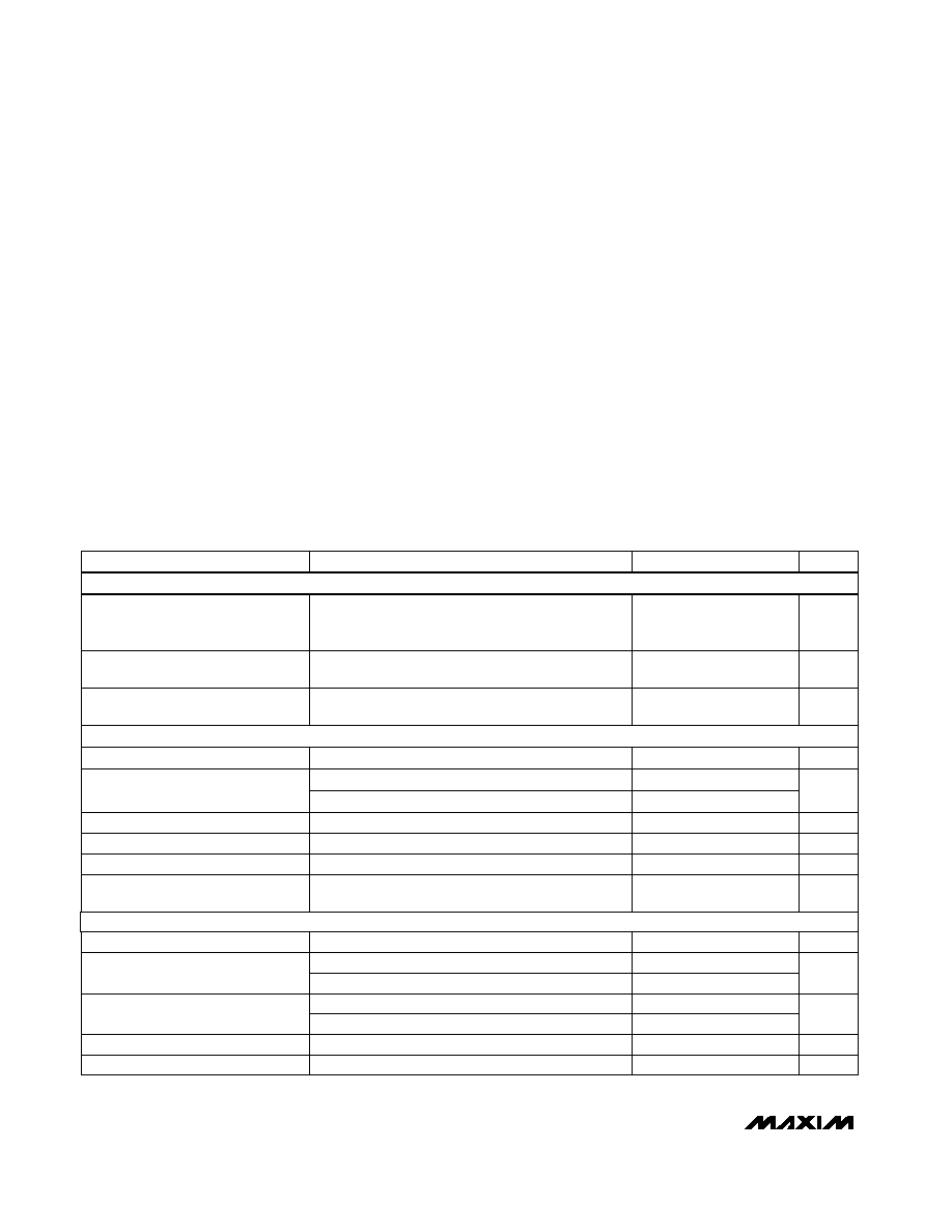
ELECTRICAL CHARACTERISTICS
(V
CC
= +3.0V to +5.5V; C1C4 = 0.1µF (tested at 3.3V ±5%), C1C4 = 0.22µF (tested at 3.3V ±10%), C1 = 0.047µF and
C2C4 = 0.33µF (tested at 5.0V ±10%); T
A
= T
MIN
to T
MAX
; unless otherwise noted. Typical values are at T
A
= +25°C.)
Stresses beyond those listed under "Absolute Maximum Ratings" may cause permanent damage to the device. These are stress ratings only, and functional
operation of the device at these or any other conditions beyond those indicated in the operational sections of the specifications is not implied. Exposure to
absolute maximum rating conditions for extended periods may affect device reliability.
V
CC
...........................................................................-0.3V to +6V
V+ (Note 1) ...............................................................-0.3V to +7V
V- (Note 1) ................................................................+0.3V to -7V
V+ + |V-| (Note 1) .................................................................+13V
Input Voltages
T_IN,
FORCEOFF, FORCEON ..............................-0.3V to +6V
R_IN .................................................................................±25V
Output Voltages
T_OUT...........................................................................±13.2V
R_OUT,
INVALID ....................................-0.3V to (V
CC
+ 0.3V)
Short-Circuit Duration
T_OUT (one at a time) ............................................Continuous
Continuous Power Dissipation (T
A
= +70°C)
SSOP (derate 9.52mW/°C above +70°C) ....................762mW
Operating Temperature Ranges
MAX3238CAI ......................................................0°C to +70°C
MAX3238EAI....................................................-40°C to +85°C
Storage Temperature Range ............................-65°C to +160°C
Lead Temperature (soldering, 10sec) ............................+300°C
FORCEOFF = GND, T
A
= +25°C
V
CC
= 3.3V or 5.0V, T
A
= +25°C, receivers idle,
transmitters idle, FORCEON = GND,
FORCEOFF = V
CC
I
OUT
= -1.0mA
I
OUT
= 1.6mA
Receivers disabled
T_IN, FORCEON,
FORCEOFF
FORCEON =
FORCEOFF = V
CC
, no load
T_IN, FORCEON,
FORCEOFF
V
CC
= 3.3V
CONDITIONS
µA
1.0
10
Supply Current, Shutdown
µA
1.0
10
Supply Current, AutoShutdown Plus
V
V
CC
-
V
CC
-
0.6
0.1
Output Voltage High
V
0.4
Output Voltage Low
µA
±0.05
±10
Output Leakage Current
µA
±0.01
±1.0
Input Leakage Current
mA
0.5
2.0
Supply Current, AutoShutdown Plus
Disabled
V
0.8
Input Logic Threshold Low
V
2.0
Input Logic Threshold High
UNITS
MIN
TYP
MAX
PARAMETER
Note 1:
V+ and V- can have a maximum magnitude of +7V, but their absolute difference can not exceed +13V.
V
CC
= 5.0V
2.4
V
-25
25
Input Voltage Range
V
CC
= 3.3V
0.6
1.2
V
CC
= 5.0V
V
0.8
1.5
Input Threshold Low
V
CC
= 3.3V
1.5
2.4
V
CC
= 5.0V
V
1.8
2.4
Input Threshold High
V
0.3
Input Hysteresis
T
A
= +25°C
k
3
5
7
Input Resistance
DC CHARACTERISTICS
LOGIC INPUTS AND RECEIVER OUTPUTS
RECEIVER INPUTS

MAX3238
+3.0V to +5.5V, 1µA, up to 250kbps, True
RS-232 Transceiver with AutoShutdown PlusTM
_______________________________________________________________________________________
3
ELECTRICAL CHARACTERISTICS (continued)
(V
CC
= +3.0V to +5.5V; C1C4 = 0.1µF (tested at 3.3V ±5%), C1C4 = 0.22µF (tested at 3.3V ±10%), C1 = 0.047µF and
C2C4 = 0.33µF (tested at 5.0V ±10%); T
A
= T
MIN
to T
MAX
; unless otherwise noted. Typical values are at T
A
= +25°C.)
Figure 4a
Figure 7a
Figure 4b (Note 2)
V
CC
= 5V, Figure 4b (Note 2)
V
CC
= 5V, Figure 4b
I
OUT
= 1.6mA
I
OUT
= -1.0mA
V
CC
= 5V, Figure 4b
CONDITIONS
V
-0.3
0.3
Receiver Input Threshold to
INVALID Output Low
V
2.7
Receiver Input Threshold to
INVALID Output High
sec
15
30
60
Receiver or Transmitter Edge to
Shutdown (t
AUTOSHDN
)
µs
25
Receiver or Transmitter Edge to
Transmitters Enabled (t
WU
)
µs
50
Receiver Positive or Negative
Threshold to
INVALID Low (t
INVL
)
V
0.4
INVALID Output Voltage Low
V
V
CC -
0.6
INVALID Output Voltage High
µs
0.1
Receiver Positive or Negative
Threshold to
INVALID High (t
INVH
)
UNITS
MIN
TYP
MAX
PARAMETER
Positive threshold
Negative threshold
-2.7
Output Voltage Swing
All transmitter outputs loaded with 3k
to ground
±5.0
±5.4
V
Output Resistance
V
CC
= V+ = V- = GND, T
OUT
= 2V
300
10M
V
CC
3.6V
±35
±60
Output Leakage Current
V
OUT
= ±12V, V
CC
= 0V to 5.5V,
transmitters disabled
±25
µA
| t
PHL
- t
PLH
|
4
30
t
PHL
R_IN to R_OUT,
C
L
= 150pF
t
PLH
C
L
= 150pF to 1000pF
R
L
= 3k
, C
L
= 1000pF, one transmitter switching
C
L
= 150pF to 2500pF
0.15
V
CC
= 3.3V,
T
A
= +25°C,
R
L
= 3
to 7k
,
measured from +3V to
-3V or -3V to +3V
Normal operation
Normal operation
| t
PHL
- t
PLH
|
µs
0.15
Receiver Propagation Delay
kbps
250
Maximum Data Rate
V/µs
6
30
Transition-Region Slew Rate
ns
200
Receiver Output Enable Time
ns
200
Receiver Output Disable Time
ns
100
Transmitter Skew
ns
50
Receiver Skew
TIMING CHARACTERISTICS
Output Short-Circuit Current
V
CC
> 3.6V
±40
±100
AutoShutdown
(FORCEON = GND,
FORCEOFF = V
CC
)
TRANSMITTER OUTPUTS
Note 2:
A transmitter/receiver edge is defined as a transition through the transmitter/receiver input logic thresholds.
mA

______________________________________________________________Pin Description
7.5
-5.0
-7.5
0
1000
3000
5000
TRANSMITTER OUTPUT VOLTAGE
vs. LOAD CAPACITANCE
-2.5
5.0
MAX3238 TOC-01
LOAD CAPACITANCE (pF)
TRANSMITTER OUTPUT VOLTAGE (V)
2000
4000
2.5
0
V
OUT
+
V
OUT
FOR DATA RATES UP TO 250kbps
1 TRANSMITTER 250kbps
4 TRANSMITTERS 15.6kbps
LOADED 3k
+
C
L
14
4
2
0
0
1000
3000
5000
SLEW RATE
vs. LOAD CAPACITANCE
6
12
MAX3238-02
SLEW RATE (V/
µ
s)
LOAD CAPACITANCE (pF)
2000
4000
10
8
+SLEW
SLEW
1 TRANSMITTER 250kbps
4 TRANSMITTERS 15.6kbps
LOADED 3k
+
C
L
70
20
10
0
0
1000
3000
5000
SUPPLY CURRENT vs. LOAD CAPACITANCE
WHEN TRANSMITTING DATA
30
60
MAX3238 TOC-03
SUPPLY CURRENT (mA)
LOAD CAPACITANCE (pF)
2000
4000
50
40
250kbps
120kbps
20kbps
__________________________________________Typical Operating Characteristics
(V
CC
= +3.3V, 250kbps data rate, 0.1µF capacitors, all transmitters loaded with 3k
, T
A
= +25°C, unless otherwise noted.)
MAX3238
+3.0V to +5.5V, 1µA, up to 250kbps, True
RS-232 Transceiver with AutoShutdown PlusTM
4
_______________________________________________________________________________________
Positive Terminal of Voltage-Doubler Charge-Pump Capacitor
C1+
28
+5.5V Generated by the Charge Pump
V+
27
+3.0V to +5.5V Supply Voltage
V
CC
26
NAME
FUNCTION
1
C2+
Positive Terminal of Inverting Charge-Pump Capacitor
2
GND
Ground
PIN
3
C2-
Negative Terminal of Inverting Charge-Pump Capacitor
4
V-
-5.5V Generated by the Charge Pump
14
FORCEOFF
Force-Off Input. Drive low to shut down transmitters, receivers (except R1OUTB), and on-
board supply. This overrides AutoShutdown Plus and FORCEON (Table 1).
13
FORCEON
Force-Off Input. Drive high to override AutoShutdown Plus, keeping transmitters and
receivers on (
FORCEOFF must be high) (Table 1).
8, 9, 11
R_IN
RS-232 Receiver Inputs (R1INR3IN)
5, 6, 7, 10, 12
T_OUT
RS-232 Transmitter Outputs (T1OUTT5OUT)
25
C1-
Negative Terminal of Voltage-Doubler Charge-Pump Capacitor
18, 20, 21
R_OUT
TTL/CMOS Receiver Outputs (R3OUTR1OUT)
17, 19, 22, 23, 24
T_IN
TTL/CMOS Transmitter Inputs (T5INT1IN)
16
R1OUTB
Noninverting Complementary Receiver Output. Always active.
15
INVALID
Output of the Valid Signal Detector. A logic "1" indicates if a valid RS-232 level is present
on receiver inputs.

MAX3238
+3.0V to +5.5V, 1µA, up to 250kbps, True
RS-232 Transceiver with AutoShutdown PlusTM
_______________________________________________________________________________________
5
_______________Detailed Description
Dual Charge-Pump Voltage Converter
The MAX3238's internal power supply consists of a reg-
ulated dual charge pump that provides output voltages
of +5.5V (doubling charge pump) and -5.5V (inverting
charge pump), regardless of the input voltage (V
CC
)
over the 3.0V to 5.5V range. The charge pumps operate
in a discontinuous mode: if the output voltages are less
than 5.5V, the charge pumps are enabled; if the output
voltages exceed 5.5V, the charge pumps are disabled.
Each charge pump requires a flying capacitor (C1, C2)
and a reservoir capacitor (C3, C4) to generate the V+
and V- supplies.
RS-232 Transmitters
The transmitters are inverting level translators that con-
vert CMOS-logic levels to 5.0V EIA/TIA-232 levels. The
MAX3238 transmitters guarantee a 250kbps data rate
with worst-case loads of 3k
in parallel with 1000pF,
providing compatibility with PC-to-PC communication
software (such as LapLinkTM). Transmitters can be par-
alleled to drive multiple receivers. Figure 1 shows a
complete system connection.
LapLink is a trademark of Traveling Software.
When
FORCEOFF is driven to ground, the transmitters
and receivers are disabled and the outputs go high
impedance, except for R1OUTB. When the Auto-
Shutdown Plus circuitry senses that all receiver and
transmitter inputs are inactive for more than 30sec, the
transmitters are disabled and the outputs go into a
high-impedance state, but the receivers remain active.
When the power is off, the MAX3238 permits the out-
puts to be driven up to ±12V.
The transmitter inputs do not have pull-up resistors.
Connect unused inputs to GND or V
CC
.
RS-232 Receivers
The receivers convert RS-232 signals to CMOS-logic
output levels. All receivers have inverting three-state
outputs and are inactive in shutdown (
FORCEOFF)
(Table 1). The MAX3238 also features an extra, always-
active noninverting output, R1OUTB. This extra output
monitors receiver activity while the other receivers are
high impedance, allowing Ring Indicator to be moni-
tored without forward biasing other devices connected
to the receiver outputs. This is ideal for systems where
V
CC
is set to 0V in shutdown to accommodate peripher-
als, such as UARTs (Figure 2).
Table 1. Output Control Truth Table
FORCEON
FORCEOFF
AUTOSHUTDOWN
PLUS*
OPERATION
STATUS
T_OUT
R_OUT
R1OUTB
X
0
X
Shutdown
(Forced Off)
High-Z
High-Z
Active
1
1
X
Normal Operation
(Forced On)
Active
Active
Active
0
1
<30sec*
Normal
Operation
(AutoShutdown
Plus)
Active
Active
Active
0
1
>30sec*
Shutdown
(AutoShutdown
Plus)
High-Z
Active
Active
X = Don't Care
* Time since last receiver or transmitter input transition.