General Description
The MAX2003/MAX2003A are fast-charge battery charg-
ers (with conditioning) for NiCd (nickel cadmium) or
NiMH (nickel-metal hydride) rechargeable batteries. The
MAX2003A has the same features as the MAX2003 with
an additional pulsed trickle-charge mode to prevent den-
drite formation in NiMH batteries. Each can be config-
ured as a switch-mode current regulator or as a gating
controller for an external current source. Switch-mode
current regulation provides efficient energy transfer,
reducing power dissipation and the associated heating.
Gating control of an external current source requires
minimal components, saving space and cost.
On-chip algorithms determine charge termination, so the
MAX2003/MAX2003A can be used as stand-alone
chargers. Fast-charge termination is accomplished by
five methods: temperature slope, negative voltage
change, maximum temperature, maximum time, and
maximum voltage. As a safety feature, the start of fast-
charge is inhibited until battery voltage and temperature
are within safe limits. By selecting the appropriate
charge-termination method, a single circuit can be built
with the MAX2003/MAX2003A to fast-charge both NiMH
and NiCd batteries.
The MAX2003/MAX2003A provide a switch-activated
discharge-before-charge option that allows for battery
conditioning and more accurate capacity measure-
ment. Other features include optional top-off charging
and direct drivers for LED status lights.
The MAX2003, in DIP and wide SO packages, is a direct
plug-in replacement for the bq2003. The MAX2003/
MAX2003A also come in a space-saving narrow SO
package. The MAX2003A evaluation kit (MAX2003A
EVKIT-SO) is available to assist in designs.
________________________Applications
Battery-Powered Equipment:
Laptop, Notebook, and Palmtop Computers
Handy-Terminals
Portable Consumer Products:
Portable Stereos
Cordless Phones
Backup-Battery Applications:
Memory Hold-Up
Emergency Switchovers
____________________________Features
o
Stand-Alone NiCd or NiMH Fast Chargers
o
New Pulsed Trickle-Charge Mode (MAX2003A only)
o
Provide Switch-Mode, Gated, or Linear Control
Regulation
o
Small, Narrow SO Package Available
o
On-Chip Fast-Charge Termination Methods:
À Temperature Slope
À Maximum Voltage
À Negative Delta Voltage
À Maximum Time
À Maximum Temperature
o
Automatically Switch from Fast-Charge to
Trickle-Charge or Top-Off Charge
o
Optional Discharge-Before-Charge
o
Directly Drive Status LEDs
o
Optional Top-Off Charge
MAX2003/MAX2003A
NiCd/NiMH Battery
Fast-Charge Controllers
________________________________________________________________
Maxim Integrated Products
1
19-0371; Rev 4; 5/97
PART
MAX2003
CPE
MAX2003CSE
0░C to +70░C
0░C to +70░C
TEMP. RANGE
PIN-PACKAGE
16 Plastic DIP
16 Narrow SO
___________________Pin Configuration
16
15
14
13
12
11
10
9
1
2
3
4
5
6
7
8
V
CC
DIS
MOD
CHG
TM1
DVEN
DCMD
CCMD
TOP VIEW
MAX2003
MAX2003A
TEMP
MCV
TCO
SNS
V
SS
BAT
TS
TM2
DIP/SO
MAX2003CWE
MAX2003C/D
0░C to +70░C
0░C to +70░C
16 Wide SO
Dice*
* Contact factory for dice specifications.
EVALUATION KIT MANUAL
FOLLOWS DATA SHEET
MAX2003A
CPE
MAX2003ACSE
MAX2003ACWE
MAX2003AC/D
0░C to +70░C
0░C to +70░C
16 Plastic DIP
16 Narrow SO
0░C to +70░C
0░C to +70░C
16 Wide SO
Dice*
Ordering Information
For free samples & the latest literature: http://www.maxim-ic.com, or phone 1-800-998-8800.
For small orders, phone 1-800-835-8769.
MAX2003/MAX2003A
NiCd/NiMH Battery
Fast-Charge Controllers
2
_______________________________________________________________________________________
ABSOLUTE MAXIMUM RATINGS
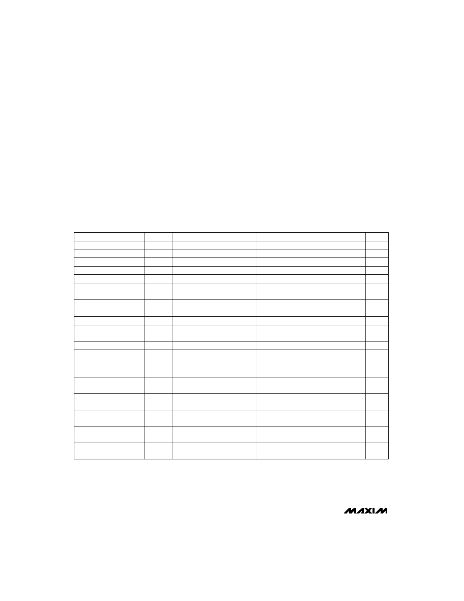
ELECTRICAL CHARACTERISTICS
(V
CC
= 4.5V to 5.5V, Figure 1, all measurements are with respect to V
SS
, T
A
= T
MIN
to T
MAX
, unless otherwise noted.)
Stresses beyond those listed under "Absolute Maximum Ratings" may cause permanent damage to the device. These are stress ratings only, and functional
operation of the device at these or any other conditions beyond those indicated in the operational sections of the specifications is not implied. Exposure to
absolute maximum rating conditions for extended periods may affect device reliability.
All Pins to V
SS
...........................................................-0.3V, +6.0V
Continuous Power Dissipation (T
A
= +70░C)
Plastic DIP (derate 10.53mW/░C above +70░C) ...........842mW
Narrow SO (derate 8.70mW/░C above +70░C) .............696mW
Wide SO (derate 9.52mW/░C above +70░C).................762mW
Operating Temperature Range...............................0░C to +70░C
Storage Temperature Range .............................-65░C to +150░C
Lead Temperature (soldering, 10sec) .............................+300░C
V
BAT
- V
SNS
No load
V
CC
= 5V
V
CC
= 5V, V
TCO
= 1.4V
V
CC
= 5V
V
CC
= 5V
V
CC
= 5V
V
CC
= 5V
V
TS
- V
SNS
V
CC
= 5V
V
CC
= 5V
CONDITIONS
mV
16
V
THERM
Thermistor Input Resolution
(Note 2)
mV
12
-
V
Negative Delta Voltage
(Note 2)
mV
30
V
SNSHI -
V
SNSLO
Delta Sense Voltage
(Note 1)
V
0.044V
CC
0.044V
CC
- 25mV
0.044V
CC
+ 25mV
V
SNSLO
Sense Trip Threshold Low
V
0.05V
CC
0.05V
CC
- 25mV
0.05V
CC
+ 25mV
V
SNSHI
Sense Trip Threshold High
V
0.0
V
CC
V
CELL
Cell Potential
mA
0.75
2.2
I
CC
V
4.5
5.0
5.5
V
CC
Supply Voltage
Supply Current
V
(V
LTF
/8)
(V
LTF
/8)
(V
LTF
/8)
+ (7V
TCO
/8)
+ 7V
TCO
/8
+ (7V
TCO
/8)
- 30mV
+ 30mV
V
HTF
High-Temperature
Trip Threshold
V
V
LTF
- 0.2V
CC
V
LTF
V
TCO
Temperature Cutoff Voltage
V
0.4V
CC
0.4V
CC
- 30mV
0.4V
CC
+ 30mV
V
LTF
Low-Temperature
Trip Threshold
V
V
EDV
V
EDV
+ 0.2V
CC
V
MCV
Maximum Cell Voltage
V
0.0
V
CC
V
BAT
Battery Voltage Input
V
0.0
V
CC
V
TEMP
Temperature Potential
V
0.0
V
CC
V
TS
Temperature Sense
Input Voltage
UNITS
MIN
TYP
MAX
SYMBOL
PARAMETER
V
CC
= 5V
V
0.2V
CC
0.2V
CC
- 30mV
0.2V
CC
+ 30mV
V
EDV
End-of-Discharge Voltage
MAX2003/MAX2003A
NiCd/NiMH Battery
Fast-Charge Controllers
_______________________________________________________________________________________
3
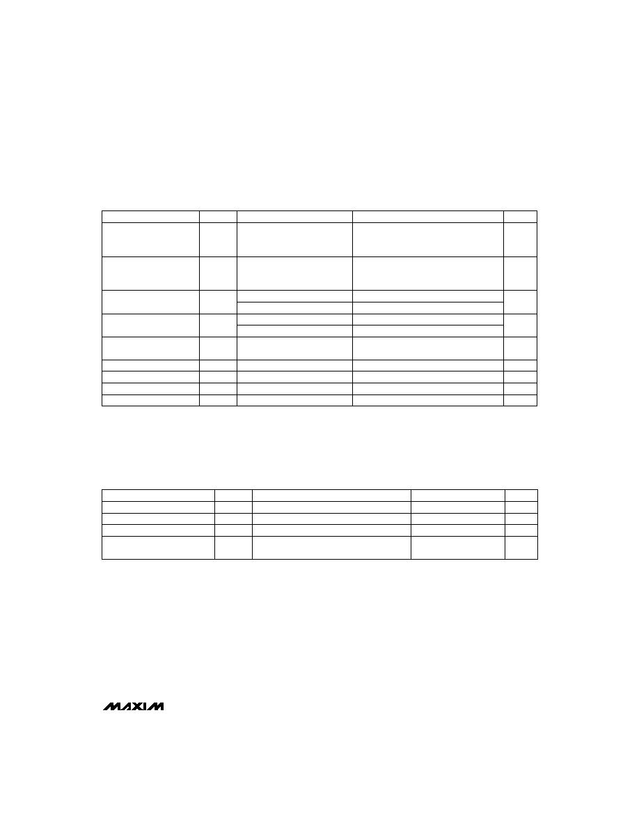
ELECTRICAL CHARACTERISTICS (continued)
(V
CC
= 4.5V to 5.5V, Figure 1, all measurements are with respect to V
SS
, T
A
= T
MIN
to T
MAX
, unless otherwise noted.)
TIMING CHARACTERISTICS
(V
CC
= 4.5V to 5.5V, Figure 1, all measurements are with respect to V
SS
, T
A
= T
MIN
to T
MAX
, unless otherwise noted. Typical values
are at V
CC
= 5.0V, T
A
= +25░C.)
Note 3:
Ratio of actual versus expected timeout (see Table 4). Tested with TM1 = TM2 = floating.
Note 4:
To recognize a battery insert signal, V
BAT
must be greater than V
MCV
for at least t
BTO
.
MOD pin in fast-charge mode, V
CC
= 5V
(Note 3)
CCMD, DCMD
CONDITIONS
kHz
100
f
MAX
MOD Switching Frequency
0.84
1.00
1.16
Ás
1.0
t
MPW
Minimum Pulse Width
Variation of Fast-Charge Timeout
UNITS
MIN
TYP
MAX
SYMBOL
PARAMETER
CCMD, DCMD,
DVEN at V
CC
and V
SS
CCMD, DCMD, DVEN
CCMD, DCMD, DVEN
TM1, TM2 = V
CC
TM1, TM2 = V
SS
For DIS, TEMP and CHG,
0mA
I
LOAD
5mA; For MOD,
0mA
I
LOAD
10mA
ÁA
-1.0
1.0
I
LKG
Input Logic Leakage
1.0
V
CC
- 1.0
V
IH
Input Logic Voltage High
ÁA
-70.0
I
IH
Input Logic Current High
ÁA
70.0
I
IL
Input Logic Current Low
V
V
CC
- 0.5
V
OH
Logic-High Threshold
TM1, TM2 = tri-state
BAT, MCV, TCO, SNS, TS
ÁA
-2.0
2.0
I
IZ
Input Logic Current High-Z
M
50
Input Impedance
TM1, TM2
V
V
CC
- 0.3
TM1, TM2
V
0.3
V
IL
Input Logic Voltage Low
ms
200
250
300
t
BTO
Battery Replacement Timeout
(Note 4)
Note 1:
The sense trip levels are determined by an internal resistor divider network that provides a typical difference of 30mV from
SNSHI to SNSLO. Slight variation in this delta is seen if there is a resistor mismatch in the network.
Note 2:
Typical variations of Negative Delta Voltage and Thermistor Input Resolution parameters are less than ▒4mV.
For DIS, TEMP and CHG,
0mA
I
LOAD
5mA; For MOD,
0mA
I
LOAD
10mA
V
0.5
V
OL
Logic-Low Threshold
CONDITIONS
UNITS
MIN
TYP
MAX
SYMBOL
PARAMETER
MAX2003/MAX2003A
NiCd/NiMH Battery
Fast-Charge Controllers
4
_______________________________________________________________________________________
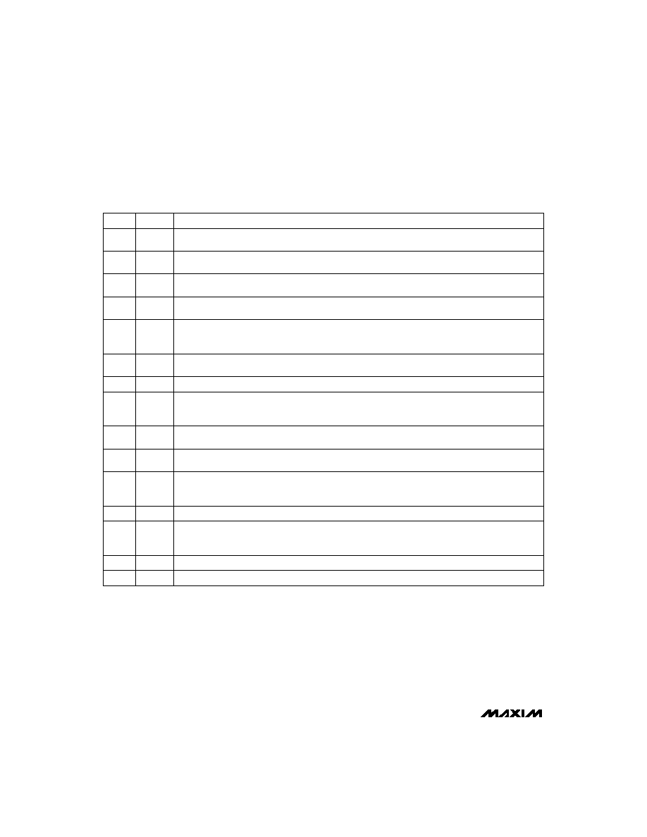
______________________________________________________________Pin Description
NAME
FUNCTION
1
CCMD
Charge-Enabled Mode Input--initiates fast-charge on a digital signal (see
Detailed Description for operating
conditions).
2
DCMD
Discharge-Enable Mode Input--initiates discharge-before-charge on a digital signal (see
Detailed
Description for operating conditions).
PIN
3
DVEN
Negative Delta Voltage (-
V) Enable Input--enables -
V charge-termination mode. If DVEN is high, the con-
troller uses negative-voltage change detection to terminate charge. If DVEN is low, this mode is disabled.
4, 5
TM1,
TM2
These inputs are used to program the fast-charge and hold-off times, and to enable the top-off charge
mode. The inputs can be high, low, or floating. See Table 4 for details.
9
SNS
Current-Sense Input--connected to the negative battery terminal. TS and BAT are referenced to this pin.
The voltage at SNS is directly proportional to the current through the battery and is used to determine how
and when MOD switches.
8
V
SS
Ground
7
BAT
Input Voltage of Single Battery Cell. If more than one cell is present, a resistor divider is needed to divide the
voltage down to a single cell voltage.
6
TS
Temperature Sense-Voltage Input from external thermistor. The thermistor temperature coefficient is nega-
tive, so the higher the temperature, the lower the voltage at this pin (See
Detailed Description for conditions
of operation).
14
MOD
Modulation Output. This push/pull output switches to enable or disable charging current. If MOD is high,
current is enabled. If it is low, current is disabled. For a 5V supply, if the voltage at the SNS pin is less than
220mV, MOD is high. If the voltage is above 250mV, MOD is low.
13
CHG
Charge Status Output. This push/pull LED driver indicates charge status (see
Detailed Description).
12
TEMP
Temperature Status Output. This push/pull LED driver indicates that the temperature is outside the accept-
able limits, and fast-charge and top-off are inhibited (see
Maximum Temperature Termination section in
Detailed Description).
11
MCV
Maximum Cell Voltage Input. If the voltage from BAT to SNS exceeds the voltage at MCV, fast or top-off
charging is terminated.
10
TCO
Temperature Cutoff-Voltage Input. If the voltage from TS to SNS is less than the voltage at TCO, a hot ther-
mistor (negative coefficient) is detected and fast or top-off charging is terminated.
16
V
CC
Power-Supply Voltage Input (+5V nominal). Bypass with a 0.1ÁF capacitor placed close to the device.
15
DIS
Discharge-Switch Control Output. This push/pull output turns on the FET that discharges the battery.
MAX2003/MAX2003A
NiCd/NiMH Battery
Fast-Charge Controllers
_______________________________________________________________________________________
5
MAX2003
MAX2003A
MOD
5
R1
60.4k
1k
100k
1k
R2
3.48k
R3
33.2k
14
14
16
13V/2A
DC SOURCE
R
TR
10k
(*150
(2W))
*TRICKLE-CHARGE
RATE
C/40
1N5822
1N5822
0.1
Á
F
15
6
9
7
7
1, 3, 5
2, 4, 6
10V ZENER
Q1
P
MMDF3P03HD
100
Á
H
1N5819
D
S
R
B1
100k
R
B2
20k
R
SNS
0.14
1%
(1W)
G
1700mAh
6 NiMH
R
DIS
4
(20W)
NTC
R
T
100k
R
B
100k
DISCHARGE
RATE
1C
CHARGE
RATE
1C
C
T
0.1
Á
F
1
Á
F
10k
C
B
0.1
Á
F
D
G
S
TO V
CC
R
T1
R
T2
DURACELL DR17
Q2
N
MMSF5NO3HD
* COMPONENT USED FOR MAX2003.
8, 10, 12
9, 11, 13
4
2
1
3
12
13
11
10
DIS
TS
SNS
BAT
V
SS
V
CC
V
CC
V
CC
TM2
PUSH TO
DISCHARGE
TM1
DCMD
TEMP
CHG
MCV
TC0
LED
LED
CCMD
DVEN
8
74HC04
LM317
243
22
Á
F
22
Á
F
22
Á
F
732
ADJ
5V OUT
IN
0.1
Á
F
0.1
Á
F
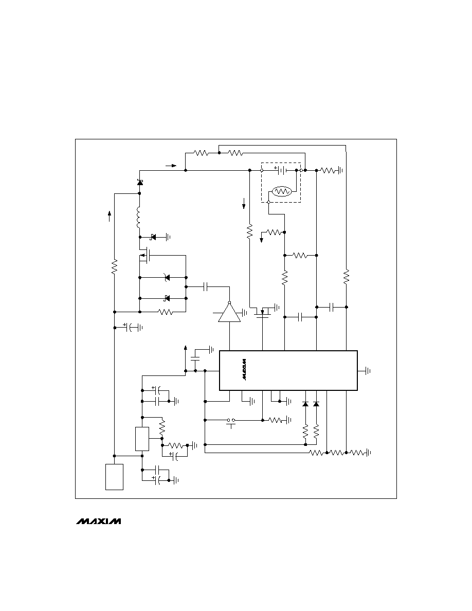
Figure 1. Switched-Mode Operation for NiMH Batteries with
T/
t Termination