
General Description
The MAX1926 evaluation kit (EV kit) is a complete, fully
assembled and tested, single-cell lithium-ion (Li+) bat-
tery charger. The EV kit provides a 4.2V output from
input as high as 12V, and delivers up to 1A charge cur-
rent. A light-emitting diode (LED) indicates the cell's
charging status.
The EV kit can be also used to evaluate the MAX1925,
which is a single-cell Li+ battery charger with a 4.5V to
6.1V input voltage charge range.
Features
o 5V to 12V Input Voltage Range
o Up to 1A Fast Charge Current
o LED Charge Status and Fault Indicator
o 12-Pin Thin QFN Package
o Surface-Mount Construction
o Fully Assembled and Tested
Quick Start
The MAX1926 EV kit is a fully assembled and tested
surface-mount board. Follow the steps below to verify
board operation. Do not turn on the power supply
until all connections are completed:
1) Verify that there is a no shunt across jumper JU1 (EN).
2) Connect a voltmeter across the EV kit's BATT and
GND pads.
3) Connect a 5V to 12V power supply to the VIN pad.
Connect the power-supply ground to the GND pad
closest to VIN.
4) Observe correct Li+ cell polarity. Connect the pos-
itive terminal of a single-cell Li+ battery to the BATT
pad. Connect the negative terminal of the battery to
the GND pad closest to BATT.
5) Turn on the power supply. The LED turns on if the
battery voltage is below 4.2V and the charging cur-
rent is above 125mA. See Table 3 for additional LED
state descriptions.
6) The LED turns off once the Li+ cell has been fully
charged.
To evaluate the MAX1925, see the Evaluating the
MAX1925 section.
Evaluates: MAX1925/MAX1926
MAX1926 Evaluation Kit
________________________________________________________________ Maxim Integrated Products
1
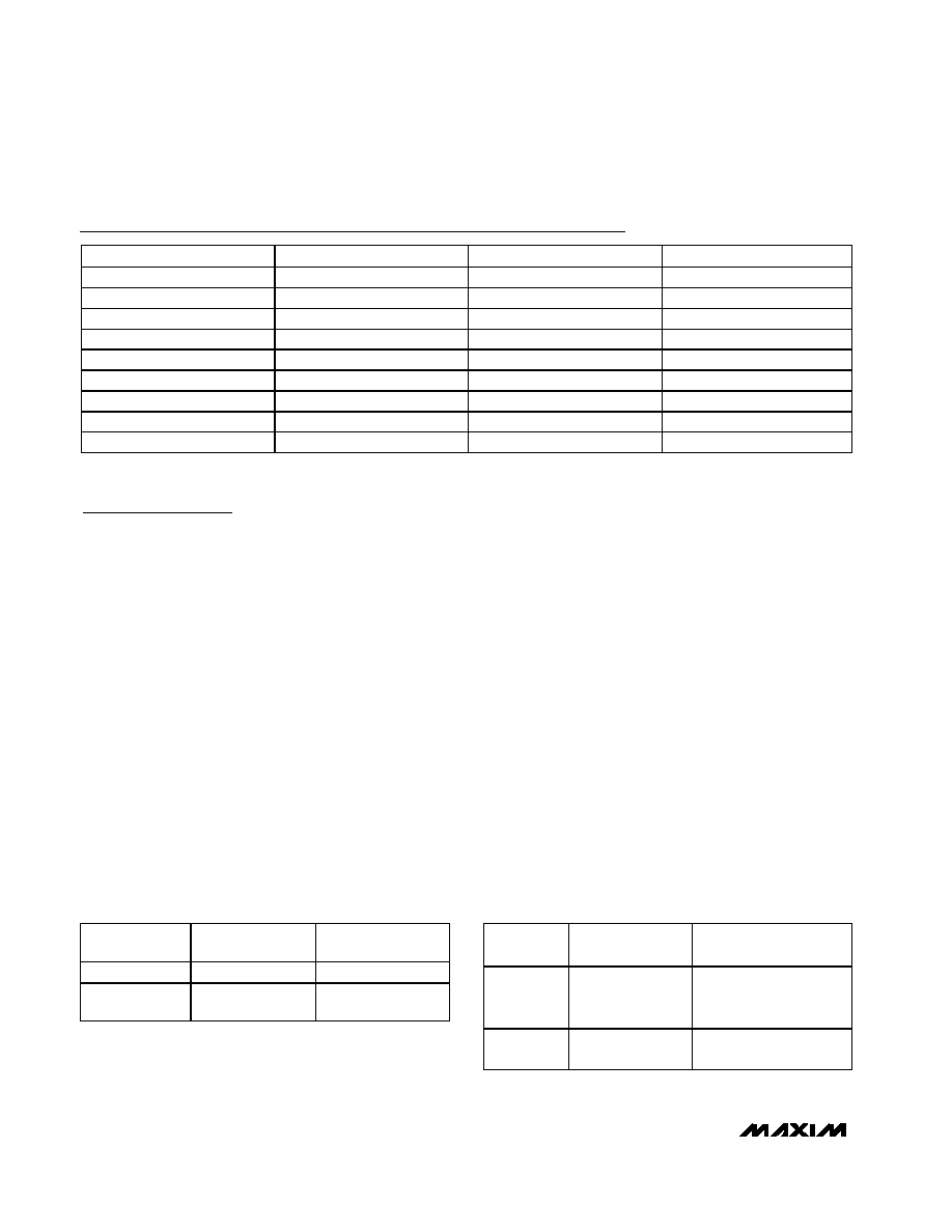
DESIGNATION QTY
DESCRIPTION
C1
1
10µF ±20%, 16V X5R
ceramic capacitor (1210)
Taiyo Yuden EMK325BJ106MN or
TDK C3225X5R1C106MT
C2
1
22µF ±20%, 6.3V tantalum capacitor
(A case)
AVX TAJA226M006R
C3
1
0.1µF ±10%, 16V X7R
ceramic capacitor (0603)
Taiyo Yuden EMK107BJ104KA or
TDK C1608X7R1C104KT or
Murata GRM39X7R104K016AD
C4
0
Not installed, capacitor (0603)
D1, D2
2
1A, 30V Schottky diodes
Nihon EP10QY03
D3
1
Surface-mount LED (0805)
JU1
1
2-pin header
JU2
0
Not installed, shorted by PC trace
L1
1
10µH, 1.3A inductor
Toko A915AY-100M or
Sumida CDRH5D28-100
Q1
1
P-channel MOSFET 3-pin SOT23
Fairchild FDN360P
R1
1
0.14
±1%, 1/2W sense resistor
(1206)
IRC LR1206-01-R140-F
R2
1
100k
±5% resistor (0603)
R3, R4
0
Not installed, resistors (0603)
R5
1
10k
±5% resistor (0603)
U1
1
MAX1926ETC 12-pin thin QFN
4mm
x
4mm, top mark AABF
None
1
Shunt
None
1
MAX1926 PC board
Ordering Information
19-2594; Rev 1; 11/02
For pricing, delivery, and ordering information, please contact Maxim/Dallas Direct! at
1-888-629-4642, or visit Maxim's website at www.maxim-ic.com.
PART
TEMP RANGE IC PACKAGE
MAX1926EVKIT
0°C to +70°C
12 Thin QFN 4mm x 4mm
Note: To evaluate the MAX1925, request a MAX1925 free sam-
ple with the MAX1926EVKIT.
Component List
Evaluates: MAX1925/MAX1926
Detailed Description
The MAX1926 EV kit is a fully assembled and tested sin-
gle-cell Li+ battery charger. The EV kit contains an exter-
nal P-channel MOSFET for current switching and can
deliver up to 1A of current to a Li+ battery. An LED indi-
cates the charging status of the battery. The maximum
charging time is set to 3 hours with 0.1µF at C3.
Jumper Selection
In the MAX1926, EN is internally pulled to 3V with an
internal 300k
resistance. When jumper JU1 is open,
EN goes to 3V and the charger is enabled. When JU1
is shorted, EN is 0V and the charger is disabled. See
Table 1 for JU1 functions
In the MAX1925, EN does not have an internal pullup
and must be driven high (5.5V max) or low. Extra pads
(R3 and R4) are provided so that EN can be driven
from a voltage-divider connected to a higher voltage
without exceeding the 5.5V limit.
Jumper JU2 provides options to connect THRM to a ther-
mistor or a 10k
resistor. The MAX1926 is disabled when
the resistance connected to THRM is greater than 28.69
or less than 3.967k
. The MAX1926 EV kit comes with
THRM connected to a 10k
resistor. JU2 is not populated
and is shorted by a PC trace. To connect a thermistor to
the EV kit, cut open the PC trace shorting JU2. Table 2
lists JU2 functions.
LED States
The LED on the EV kit is driven by the CHG pin.
Depending on the Li+ cell's charging status, the pin is
low or high impedance, thus turning the LED on or off.
The LED blinks at 0.5Hz when the MAX1926 enters
Fault Prequal1, Fault Prequal 2, Fault Full, Fault BATT
Voltage, or the Fault Temp state. For driving logic cir-
cuits, remove the LED and install a pullup resistor from
a logic supply to CHG. Table 3 lists the LED states.
Evaluating the MAX1925
To evaluate the MAX1925, replace the MAX1926ETC
with a MAX1925ETC. Install 100k
resistors R3 and R4
to enable the IC.
MAX1926 Evaluation Kit
2
_______________________________________________________________________________________
SUPPLIER
PHONE
FAX
WEBSITE
AVX
843-946-0238
843-626-3123
www.avxcorp.com
Fairchild
888-522-5372
408-882-2102
www.fairchildsemi.com
IRC
361-992-7900
361-992-3377
www.irctt.com
Murata
770-436-1300
770-436-3030
www.murata.com
Nihon
81-33343-3411
81-33342-5407
www.niec.co.jp
Sumida
847-545-6700
847-545-6720
www.sumida.com
Taiyo Yuden
800-348-2496
847-925-0899
www.t-yuden.com
TDK
847-803-6100
847-390-4405
www.component.tdk.com
Toko
847-297-0070
847-699-1194
www.tokoam.com
Component Suppliers
Note: Please indicate that you are using the MAX1925/MAX1926 when contacting these component suppliers.
SHUNT
LOCATION
EN PIN
MAX1926 OUTPUT
Installed
Connected to GND
MAX1926 is disabled
Not installed
EN internally pulled
to 3V
MAX1926 is enabled
Table 1. JU1 Functions
JUMPER
STATE
THRM PIN
MAX1926 OUTPUT
Open
Connected to a
thermistor using
THRM pad
MAX1926 enabled with
valid THRM resistance
and EN high
Shorted
(by Default)
Connect to a 10k
pulldown resistor
MAX1926 is enabled if EN
is high
Table 2. JU2 Functions
Evaluates: MAX1925/MAX1926
MAX1926 Evaluation Kit
_______________________________________________________________________________________
3
CHARGING STATE
CONDITION
LED STATE
Off
EN low, or no battery, or no wall power.
Off.
Prequal1
Charge current = 4mA until BATT reaches 2V.
On.
Prequal2
Charge current = C/10 (100mA) until BATT reaches 3V.
On.
Fast Charge
Charge current = C = 142mV/R1 (1A).
On.
Full Charge
Charge current has fallen to C/8 (125mA).
Off.
Fault Prequal1
BATT does not reach 2V before Prequal1 timeout.
Fault Prequal2
BATT does not reach 3V before Prequal2 timeout.
Fault Full
Charge current does not drop to C/8 (125mA) before full-
charge timeout.
Fault Batt Voltage
Battery voltage has exceeded 4.35V.
Blinking at 0.5Hz. Clear fault by cycling
input power, THRM, or EN.
MAX1925: Off.
Fault Temp
Temperature has risen above +50
°C or fallen below 0°C if a
thermistor is installed. Temp fault clears by itself.
MAX1926: Blinking at 0.5Hz.
None
Initial power-up or enable with no battery.
Blinking at rapid rate as charger cycles
through Reset, Prequal1, and Done.
Table 3. LED States
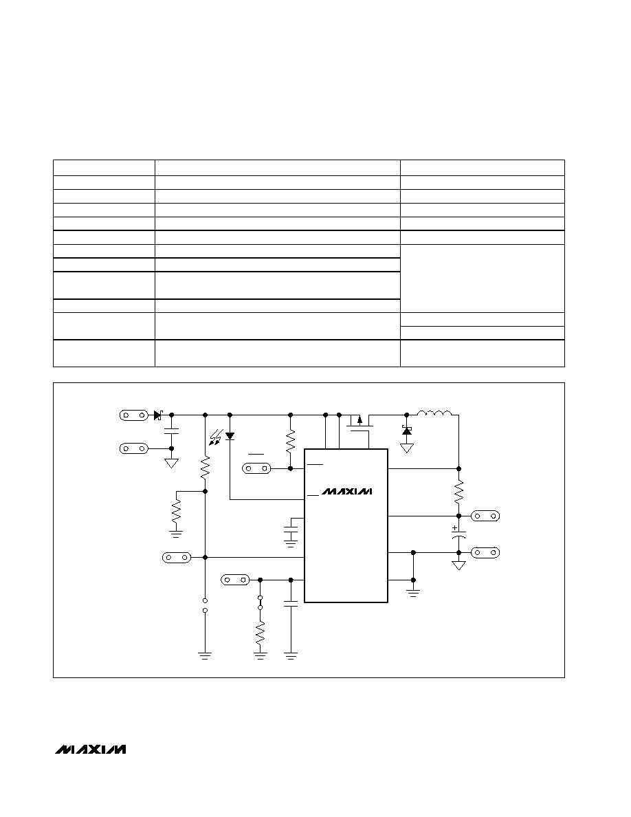
MAX1926
VIN
D1
GND
C1
10
µF
16V
R3
OPEN
R4
OPEN
D3
R2
100k
ACON
S
D
D2
G
Q1
L1
10
µH
R1
0.14
1%
BATT
GND
C2
22
µF
6.3V
C3
0.1
µF
JU1
EN
THRM
JU2
SHORTED
BY PC TRACE
R5
10k
C4
OPEN
4
1
ACON
CHG
5
CT
2
EN
3
THRM
IN
12
INP
11
EXT
10
CS
6
BATT
7
PGND
9
GND
8
U1
Figure 1. MAX1926 EV Kit Schematic
Evaluates: MAX1925/MAX1926
MAX1926 Evaluation Kit
Maxim cannot assume responsibility for use of any circuitry other than circuitry entirely embodied in a Maxim product. No circuit patent licenses are
implied. Maxim reserves the right to change the circuitry and specifications without notice at any time.
4 _____________________Maxim Integrated Products, 120 San Gabriel Drive, Sunnyvale, CA 94086 408-737-7600
© 2002 Maxim Integrated Products
Printed USA
is a registered trademark of Maxim Integrated Products.
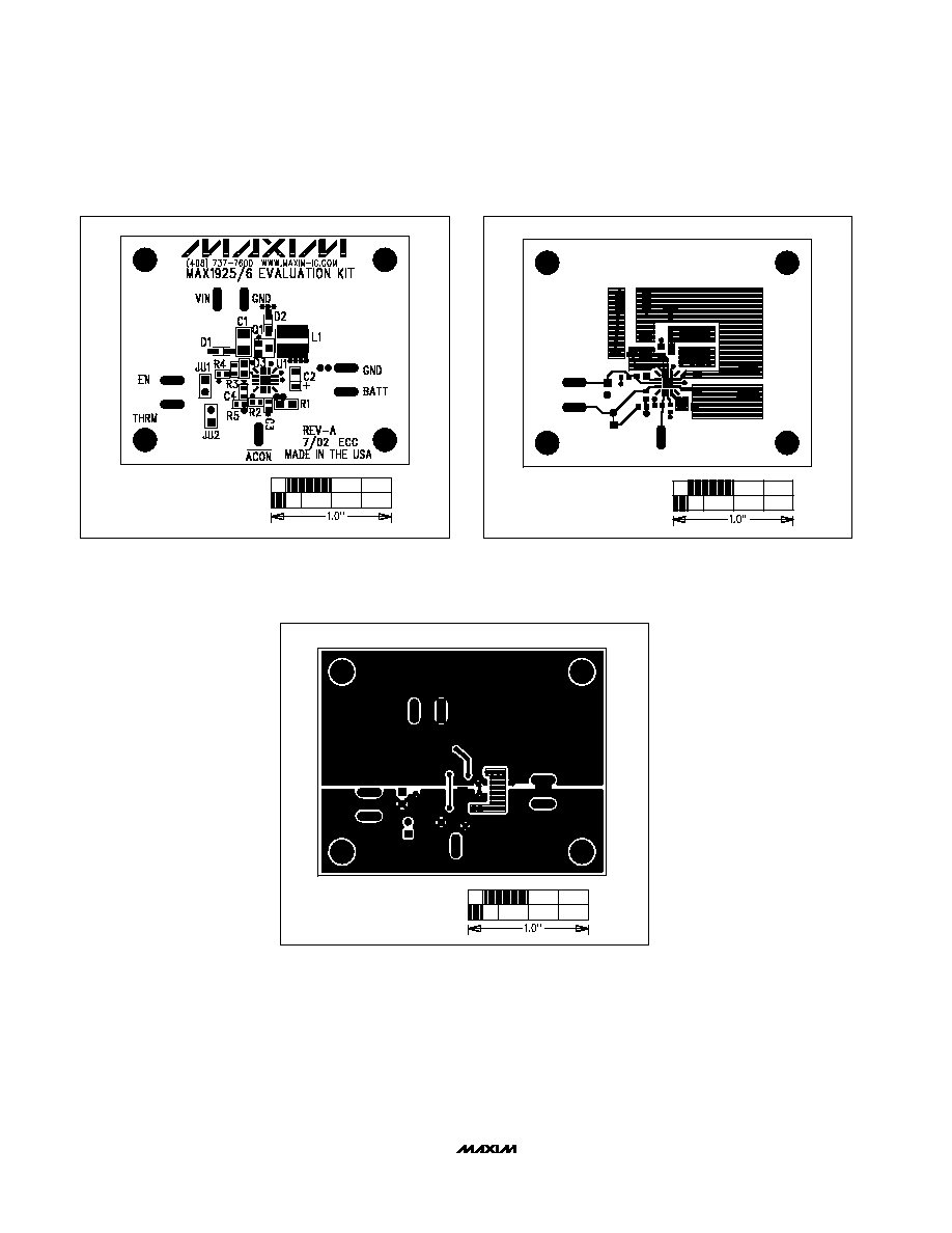
Figure 2. MAX1926 EV Kit Component Placement Guide--Top
Silkscreen
Figure 3. MAX1926 EV Kit PC Board Layout--Component Side
Figure 4. MAX1926 EV Kit PC Board Layout--Solder Side