1 of 11
REV: 060903
GENERAL DESCRIPTION
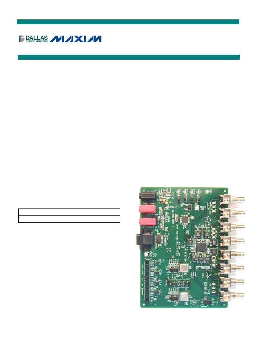
The DS3154DK is an easy-to-use evaluation kit for
the DS3154 quad DS3/E3/STS-1 LIU. A surface-
mounted DS3154 and careful layout of the analog
signal traces provide maximum signal integrity to
demonstrate the transmit and receive capabilities of
the DS3154. On-board Dallas 8051-compatible
microcontroller and included software give point-and-
click access to configuration and status registers
from a personal computer. LEDs on the board
indicate interrupt, loss-of-signal, transmit driver
monitor, and PRBS sync status for all four ports. The
board provides BNC connectors for the line-side
transmit and receive differential pairs and a 50-pin
connector for framer interface signals. All LEDs and
connectors are clearly labeled with silk-screening to
identify associated signals.
DEMO KIT CONTENTS
DS3154DK Board
CD-ROM
ChipView Software
DS3154.def Definition File
DS3154DK Data Sheet
DS3154 Data Sheet
ORDERING INFORMATION
PART DESCRIPTION
DS3154DK
DS3154 Demo Kit
FEATURES
§
Soldered DS3154 for Best Signal Integrity
§
BNC Connectors, Transformers and Termination
Passives for All Four LIUs
§
Careful Layout for Analog Signal Paths
§
Equipment-Side Connector for External Data
Source/Sink or External Remote Loopback
§
On-Board DS3 and E3 Crystal Oscillators
§
DS3154 Configured for CPU Bus Operation for
Complete Control Over the Device
§
On-Board Dallas Microcontroller and Included
Software Provide Point-and-Click Access to the
DS3154 Register Set
§
LEDs for Interrupt, Loss-of-Signal, Transmit
Driver Monitor, and PRBS Sync
§
Banana Jack Connectors for V
DD
and GND
Support Use of Lab Power Supplies
§
Separate DS3154 V
DD
to Enable I
DD
Measurements
§
Easy-to-Read Silk Screen Labels Identify the
Signals Associated with All Connectors, Jumpers
and LEDs
DS3154DK
Quad DS3/E3/STS-1 LIU Demo Kit
www.maxim-ic.com
DS3154 Demo Kit
2 of 11
COMPONENT LIST
DESIGNATION QTY
DESCRIPTION MANUFACTURER
PART
U1
1
Quad DS3/E3/STS1 LIU, 144-pin BGA
Dallas Semiconductor DS3154
U12
1
High-speed microcontroller, 44-pin TQFP Dallas
Semiconductor
DS87C520-ECL
U11
1
Dual RS232 XMITR/receiver, 16-pin SO (300-mil) Dallas Semiconductor DS232AS
U10
SO, 8-pin, step-up DC-DC converter 0.5A limit
Maxim
MAX1675EUA
U6, U7
2
Oct buffer/driver, 3.3V SOP, 20-pin narrow
Texas Instruments
SN74ALVC244NSR
U2, U4, U5
3
IC, hex inverter, SO
Toshiba
TC74HC04AFN
C1, C2, C7, C8, C14,
C24, C43, C44,
C47C60
22 0.1
mF, 25V 10% ceramic capacitors (1206)
Panasonic ECJ-3VB1E104K
C13, C15C17, C20,
C22, C23, C25, C26,
C37, C38
11 10
mF, 10V, 20% ceramic capacitors (1206)
Panasonic ECJ-3YB1A106M
C27C36, C39C42
14 0.1
mF, 16V 10% ceramic capacitors (0805)
Phycomp 08052R104K7B20D
C45, C46
2
22pF, 100V 10% ceramic capacitors (1206)
AVX
12061A220KAT2A
C18, C19
2
68
mF, 16V 20% tantalum capacitors (D case)
Panasonic ECS-T1CD686R
C3C6, C9C12
8
47,000pF, 0V 10% ceramic capacitors (1206)
Panasonic ECU-V1H473KBW
D1
1
1A, 50V diode
Generic
1N4001
DS1-DS3, DS5, DS6,
DS9, DS10, DS13,
DS14, DS18
10 LED, red, SMD
Panasonic
LN1251C
DS4, DS7, DS8,
DS11, DS12, DS16,
DS19, DS20
8
LED, green, SMD
Panasonic
LN1351C
J1
1
Connector, 10-pin, dual row, vertical
Digi-Key (Distributor) S2012-05-ND
J2J9
8
Right angle BNC
Amphenol
31-5431
J10
1
Connector, DB9 RA, short case
Amp
788750-2
J11
1
Terminal strip, 50-pin, dual row vertical
Samtec
TSW-125-07-T-D
J12, J14
2
Socket, banana plug, horizontal, red
Mouser
164-6219
J13
1
Socket, banana plug, horizontal, black
Mouser
164-6218
JMP1JMP10
10 Do not place, open 3-pin TH jumper
N/A
N/A
JMP11JMR14
4
Do not place, shorted 2-pin TH jumper
N/A
N/A
L1 1
22.0
mH, 2-pin SMT 20% inductor
Coiltronics UP1B-220
R7R12, R14, R31,
R32, R34R36, R38,
R77, R78, R83-R90,
R96R98
26 332
W 1% 1/10W resistors (0805)
Panasonic ERJ-6ENF3320V
R48R52, R60R76
22 33.2
W 1% 1/10W resistors (0805)
Panasonic ERJ-6ENF33R2V
R17, R41, R42, R46,
R55, R56, R92
7
0
W 5% 1/10W resistors (0805)
Panasonic ERJ-6GEY0R00V
R1R6, R13, R15,
R16, R18, R19, R22,
R24R30, R40, R43,
R53, R54, R79R82,
R91, R95
29
10k
W 5%, 1/10W resistors (0805)
Panasonic ERJ-6GEYJ103V
R93 1
3.9
W 5%, 1/10W resistors (0805)
Panasonic ERJ-6GEYJ3R9V
R20, R21, R23, R33,
R37, R39, R44, R45,
R47, R57R59
12 Resistors (0805), do not populate
N/A
N/A
SW1SW4
4
Switch, SPDT slide, 3-pin TH
Tyco
SSA12
SW5, SW6
2
Switch MOM 4-pin single pole
Panasonic
EVQPAE04M
T1T8
8
XFMR, XMIT/RCV, 1 to 2CT, SMT 6-pin
Pulse Engineering
PE-65968
Y1
1
Oscillator, crystal clock, 3.3V, 44.736MHz
Saronix
NTH089AA3-44.736
Y2
1
Oscillator, crystal clock, 3.3V, 34.368MHz
Saronix
NTH089AA3-34.368
Y3
1
11.0592MHz low-profile crystal
Pletronics
LP49-33-11.0592M
DS3154 Demo Kit
3 of 11
BOARD FLOORPLAN
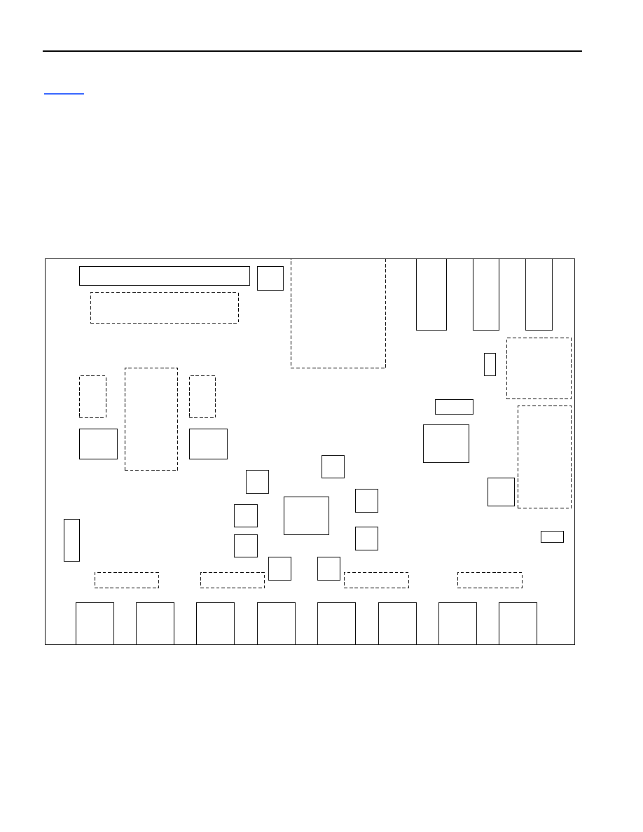
Figure 1
shows the floorplan of the DS3154DK. The DS3154 is near the center of the board, surrounded by 2:1
transformers. The line-side BNC connectors for the transmit (Tx) and receive (Rx) differential pairs are located at
the bottom of the board. LEDs driven by DS3154 pins
RLOSn, TDMn, and PRBSn are located next to the
corresponding BNC connectors. An LED driven by the DS3154's
INT pin is located to the far right. The system
connector in the upper-left corner presents all of the DS3154's framer interface pins: RCLKn, RPOSn/RDATn,
RNEG/RLCVn, TCLKn, TPOSn/TDATn, and TNEGn. In the upper-right corner are banana jacks for ground, board
V
DD
, and a separate DS3154 V
DD
(useful for DS3154 I
DD
measurements). The board also contains DS3 and E3
oscillators and the necessary jumpers to configure the DS3154 transmitters for clocking from the oscillators, from
the system connector or from the DS3154 receivers (external remote loopback). In the right-center of the board are
a DS87C520 microcontroller and associated components, including four switches and four LEDs connected to the
controller's general-purpose I/O pins. The microcontroller translates memory access requests from the RS-232
serial port (top-center of the board) into register accesses on the DS3154.
Figure 1. Board Floorplan
SYSTEM CONNECTOR
DS3154
BNC
RX4
xfrmr
BO
AR
D
V
DD
GND
DS3
OSC
INT
JT
A
G
LE
D
DS
3154
V
DD
SERIAL PORT
AND
RS-232
TRANSCEIVER
POWER-
SUPPLY
COMPONENTS
xfrmr
xfrmr
xfrmr
xfrmr
xfrmr
xfrmr
xfrmr
BNC
TX4
BNC
TX2
BNC
RX2
BNC
RX3
BNC
TX3
BNC
TX1
BNC
RX1
LEDs
LEDs
LEDs
LEDs
mC
RESET
87C520
mC
DS3/E3
CLOCK
JUMPERS
E3MCLK
T3MCLK
TCLK1
TCLK2
TCLK3
TCLK4
PW
R
LED
E3
OSC
3154
RESET
CLOCK
BU
FFER
S
CLOCK
BU
FFER
S
EXTERNAL/INTERNAL CLOCK
JUMPERS
TCLK1
TCLK2
TCLK3
TCLK4
GENERAL
PURPOSE
SWITCHES
AND LEDS
mC OSC
DS3154 Demo Kit
4 of 11
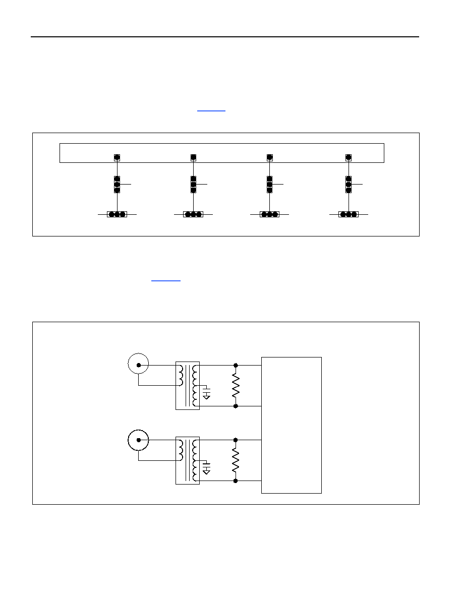
TCLK JUMPERS
Jumpers JMP7, JMP8, JMP9, and JMP10 (just below the system connector) select the clock source for the
DS3154 transmitters. The center pin on each of these jumpers is connected directly to the associated TCLK pin on
the DS3154. To drive a DS3154 TCLK pin from the system connector, connect the center pin and the EXT
(external) pin of the associated jumper. To drive a DS3154 TCLK pin from one of the on-board oscillators, connect
the center pin and the INT (internal) pin of the associated jumper. Jumpers JMP2, JMP3, JMP4, and JMP5 select
between the DS3 oscillator and the E3 oscillator (
Figure 2
).
Figure 2. TCLK Jumpers
LINE-SIDE CONNECTIONS
The DS3154DK implements the transmit (Tx) and receive (Rx) line interface networks recommended in the
DS3154 data sheet and shown in
Figure 3
. The BNC connectors for LIU1 are labeled TX1 and RX1. The BNC
connectors for LIU2 are labeled TX2 and RX2. The BNC connectors for LIU3 are labeled TX3 and RX3. The BNC
connectors for LIU4 are labeled TX4 and RX4.
Figure 3. Line-Side Circuitry
1:2ct
1:2ct
0.05
mF
TRANSMIT
RECEIVE
TXP
TXN
RXP
RXN
EACH LIU
330
W
(1%)
0.05
mF
330
W
(1%)
DS315x
DS3
OSC
E3
OSC
JMP2
DS3154
TCLK1
JMP7
TCLK1
SYSTEM
CONNECTOR
DS3
OSC
E3
OSC
JMP3
DS3154
TCLK2
TCLK2
DS3
OSC
E3
OSC
JMP4
DS3154
TCLK3
TCLK3
DS3
OSC
E3
OSC
JMP5
DS3154
TCLK4
TCLK4
EXT
INT
JMP8
EXT
INT
JMP9
EXT
INT
JMP10
EXT
INT

DS3154 Demo Kit
5 of 11
SYSTEM CONNECTOR
The 50-pin system connector at the top of the board gives access to the following DS3154 signals: STMCLK,
RCLKn, RPOSn/RDATn, RNEG/RLCVn, TCLKn, TPOSn/TDATn, and TNEGn. The system connector can be used
to connect the DS3154 to an external DS3/E3 framer or other data source/sink. By using jumpers to connect
TCLKn to RCLKn, TPOSn to RPOSn, and TNEGn to RNEGn, the system connector can also be used to implement
an external remote loopback. In addition, it can be used to wire DS3154 input pins like TPOSn and TNEGn low. To
wire a pin low, use a jumper to connect it to the neighboring GND pin on the upper row of the system connector.
MICROCONTROLLER, SWITCHES, AND LEDS
The DS87C520 microcontroller has factory-installed firmware in on-chip nonvolatile memory. This firmware
translates memory access requests from the RS-232 serial port into register accesses on the DS3154. Switches
SW1 through SW4 and LEDs DS7, DS11, DS19, and DS20 are connected to four general-purpose I/O pins on the
microcontroller. When the microcontroller starts up it turns on DS20 and leaves DS7, DS11, and DS19 off to
indicate that the controller is working correctly. Otherwise, these switches and LEDs are not used by the
DS3154DK firmware.
POWER-SUPPLY CONNECTORS
Connect a 3.3V power supply across the red J12 (DK V
DD
) and black J13 (GND) banana jacks. Connect a separate
supply to the red J14 (3154 V
DD
) and black J13 (GND). Jumpers (JMP11JMP14) are provided to measure the
device's current and can be used instead of J14. The supplies (V
DD
and V3_3) have been separated from what is
shown in the schematic (page 4, Section D-3) because switching power-supply noise is affecting generated jitter on
the DS3154. The supplies should not be wired together for any jitter peformance measurements.
CONNECTING TO A COMPUTER
Connect a standard DB-9 serial cable between the serial port on the DS3154DK and an available serial port on the
host computer. The host computer must be a Windows
®
-based PC. Be sure the cable is a standard straight-
through cable rather than a null-modem cable. Null-modem cables prevent proper operation.
INSTALLING AND RUNNING THE SOFTWARE
ChipView is a general-purpose program that supports a number of Dallas Semiconductor demo kits. To install the
ChipView software, run SETUP.EXE from the disk included in the DS3154DK box or from the zip file downloadable
on our website at
www.maxim-ic.com/DS3154DK
.
After installation, run the ChipView program with the DS3154DK board powered up and connected to the PC. If the
default installation options were used, one easy way to run ChipView is to click the Start button on the Windows
toolbar and select Programs
®ChipView®ChipView. In the opening screen, click the Register View button. (The
Demo and Terminal buttons are not supported for the DS3154DK.) Select the correct serial port in the Port
Selection dialog box, then click OK.
Next, the Definition File Assignment window appears. This window has subwindows to select definition files for up
to four separate boards on other Dallas evaluation platforms. Because ChipView is communicating with the
DS3154DK, only one subwindow is active. In the active subwindow, select the DS3154.DEF definition file from the
list shown, or browse to find it in another directory. Press the Continue button.
After selecting the definition file, the main part of the ChipView window displays the DS3154's register map. The
registers in LIU1 are displayed in the left column followed by registers for the other LIUs in subsequent columns. To
select a register, click on it in the register map. When a register is selected, the full name of the register and its bit
map are displayed at the bottom of the ChipView window. Bits that are logic 0 are displayed in white, while bits that
are logic 1 are displayed in green.
Windows is a registered trademark of Microsoft Corp.