LESHAN RADIO COMPANY, LTD.
BB135¡1/2
UHF Variable Capacitance
Diode
SOD¡ 323
1
2
BB135
P5
MARKING DIAGRAM
2
ANODE
1
CATHODE
FEATURES
À Excellent linearity
À Very small plastic SMD package.
À C28: 1.9 pF; ratio: 10
À Low series resistance.
APPLICATIONS
À Electronic tuning in UHF television
tuners.
À Radio upconversion concepts
À VCO.
DESCRIPTION
The BB135 is a variable capacitance
diode, fabricated in planar technology,
and encapsulated in the SOD323 very
small plastic SMD package.
The matched type, BB134 has the
same specification.
LIMITING VALUES
In accordance with the Absolute Maximum Rating System (IEC 134).
SYMBOL
PARAMETER
MIN.
MAX.
UNIT
V
R
continuous reverse voltage
¡
30
V
I
F
continuous forward current
¡
20
mA
T
stg
storage temperature
¡55
+150
░C
T
j
operating junction temperature
¡55
+125
░C
ELECTRICAL CHARACTERISTICS
T
j
= 25 ░C unless otherwise specified.
SYMBOL
PARAMETER
CONDITIONS
MIN.
MAX. UNIT
I
R
reverse current
V
R
= 30 V; see Fig.2
¡
10
nA
V
R
= 30 V; T
j
= 85 ░C; see Fig.2
¡
200
nA
r
s
diode series resistance
f = 470 MHz; note 1
¡
0.75
C
d
diode capacitance
V
R
= 0.5 V; f = 1 MHz; see Figs 1 and 3
17.5
21
pF
V
R
= 28 V;f = 1 MHz; see Figs 1 and 3
1.7
2.1
pF
C
d( 0.5V )
capacitance ratio
f = 1 MHz
8.9
12
C
d (28V )
Note
1. V
R
is the value at which C
d
= 9 pF.
LESHAN RADIO COMPANY, LTD.
BB135¡2/2
BB135
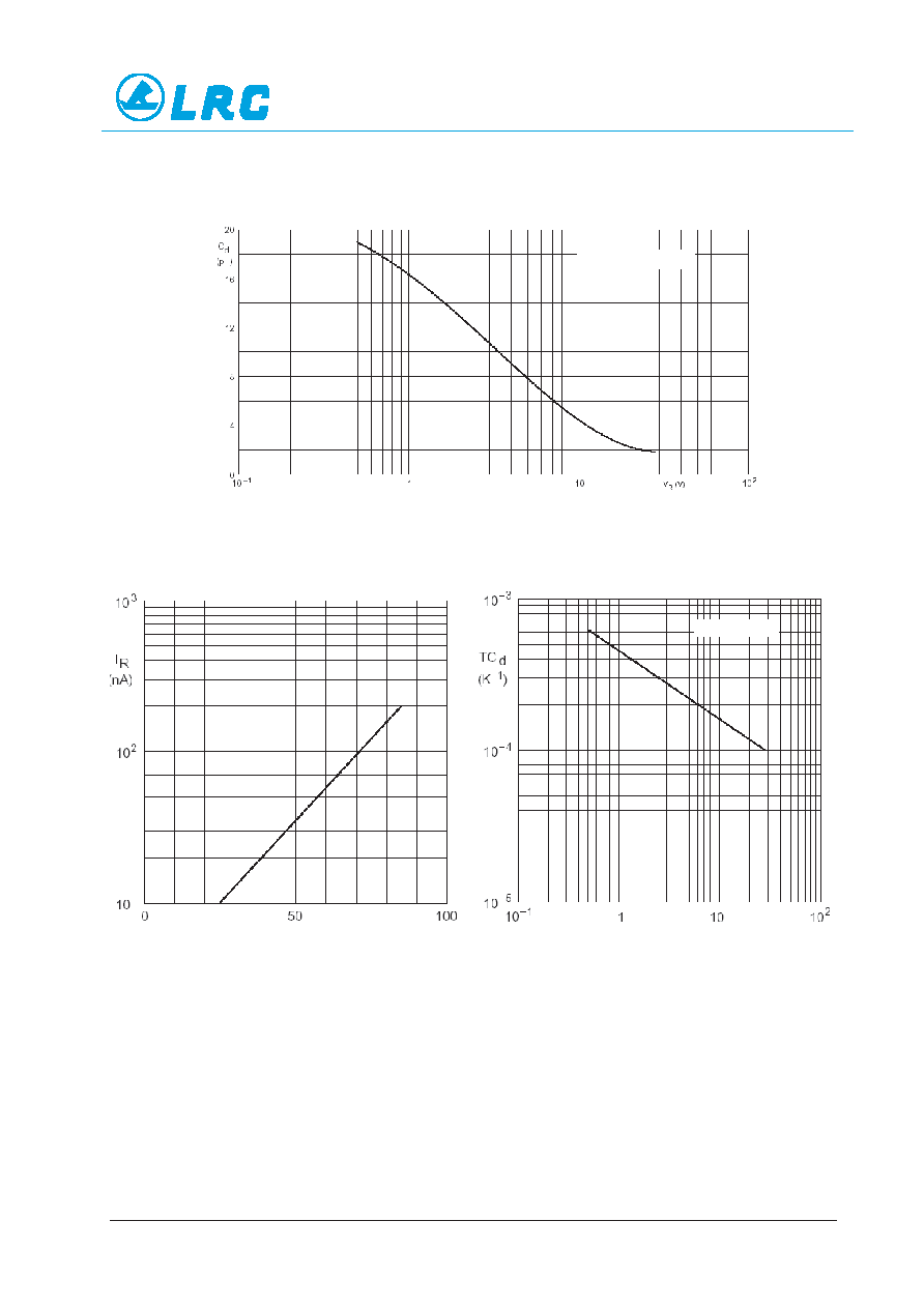
Fig.1 Diode capacitance as a function of reverse voltage; typical values.
Fig.2 Reverse current as a function of junction
temperature; maximum values.
Fig.3 Temperature coefficient of diode
capacitance as a function of
reverse voltage; typical values.
T
j
░C.
V
R
(V).
f = 1 MHz; T
j
= 25 ░C
.
T
j
= 0 to 85 ░C
.