LT1942
1
1942fa
, LTC and LT are registered trademarks of Linear Technology Corporation.
All other trademarks are the property of their respective owners.
The LT
®
1942 is a highly integrated quad switching regu-
lator designed to provide all necessary power supply
functions for TFT displays, including the white LED
backlight driver. The TFT supply incorporates two boost
and one inverting DC/DC converters. The TFT supply
output voltages are independently set, unlike charge
pump solutions which have many limitations. Power
sequencing for the TFT supply is built into the part and is
user programmable.
The LED driver is a boost DC/DC converter that can be
independently controlled. The LED driver has built-in
dimming control for precise control of LED current. An 8:1
dimming range is achieved by adjusting the CTRL4
voltage.The user can elect to drive a single string or two
strings of LEDs. An LED ballast circuit is included to
precisely match the LED currents if two strings of LEDs are
used. Soft-start is built into the LED driver as well as the
primary TFT supply.
The LT1942 is available in a low profile (0.75mm) 24-lead
QFN (4mm
× 4mm) package.
Triple Output TFT Supply with Built-In
Power Sequencing
Integrated White LED Backlight Driver
Integrated Schottky Diodes
Active Ballast Circuitry Ensures Precise Current
Matching in White LEDs
Low Noise 1MHz Fixed Frequency Operation
2.6V to 16V Input Voltage Range
Soft-Start Limits Inrush Current
TFT Supply Output Voltages Independently Set
(Not Charge Pump Derived)
Power Good and Output Disconnect for TFT Supply
Built-In LED Dimming Capability
Open LED Protection for LED Driver
24-Lead QFN Package (4mm
× 4mm)
Quad DC/DC Converter
for Triple Output TFT Supply
Plus LED Driver
Poly-Silicon TFT Displays
Amorphous Silicon TFT Displays
CTRL4
SGND/
AGND
D3
SW3
LT1942
SW1
FB1
PGND14
PGOOD
SW4
D4
LED1
LED2
FB4
FB3
PGND23
V
OUT3
NFB2
D2
SW2
0.1
µF
0.22
µF
47
µH
V
IN
47
µH
SHDN
V
CC
SS1
SS4
CT
22
µH
22
µH
CMDSH-3
Si2301BDS
33
µH
301k
1M
100k
V
IN
4.7pF
0.1
µF
0.1
µF
0.1
µF
1942 TA01
0.22
µF
0.22
µF
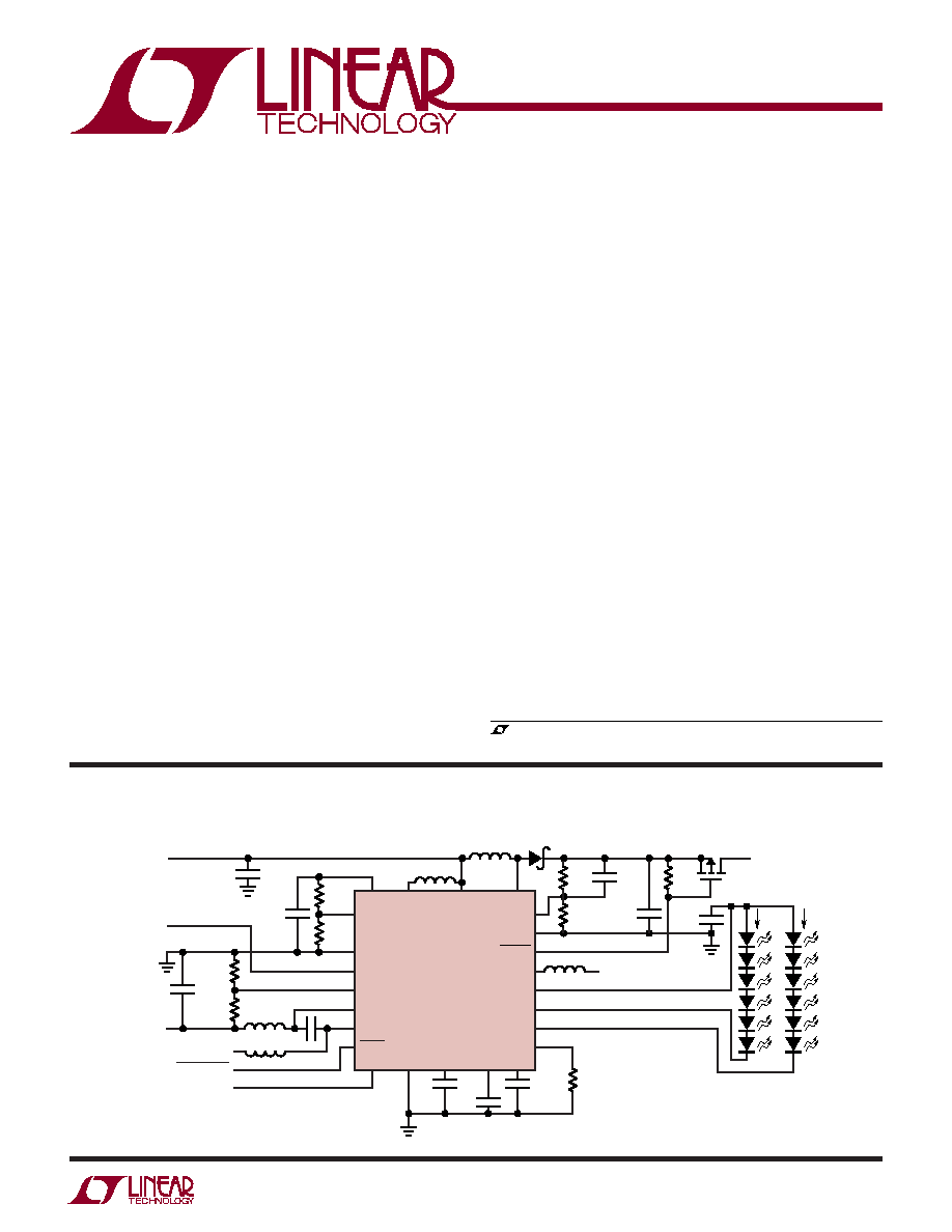
SHUTDOWN
LED CONTROL
AV
DD
5V
40mA
4.7
µF
4.7
µF
698k
100k
10k
V
IN
3V TO 4.2V
V
ON
10V
2mA
V
OFF
10V
2mA
665k
4.99
20mA
20mA
TFT Bias and White LED Backlight Power Supply
APPLICATIO S
U
DESCRIPTIO
U
FEATURES

LT1942
2
1942fa
Order Options Tape and Reel: Add #TR
Lead Free: Add #PBF Lead Free Tape and Reel: Add #TRPBF
Lead Free Part Marking:
http://www.linear.com/leadfree/
V
CC
Voltage ............................................................. 16V
SW1, SW2, SW3 Voltage .......................... 0.4V to 36V
SW4 .......................................................... 0.4V to 45V
FB1, FB3 Voltage ................................................... 2.5V
FB4 Voltage ....................................................... 400mV
NFB2 Voltage ................................................... 200mV
SHDN Voltage ......................................................... 10V
CTRL4 Voltage ........................................................ 16V
SS1, SS4 Voltage .................................................. 1.5V
Current Into D2 ......................................................... 1A
D2 Voltage ............................................................ 36V
Current Out of D3 ..................................................... 1A
D3 Voltage .............................................................. 36V
Current Out of D4 ..................................................... 4A
D4 Voltage .............................................................. 45V
LED1, LED2 Voltage ............................................... 45V
Current Into LED1, LED2 ..................................... 35mA
PGOOD Voltage ...................................................... 16V
V
OUT3
Voltage ......................................................... 36V
CT Current ...........................................................
±1mA
Maximum Junction Temperature ......................... 125
°C
Operating Temperature Range (Note 2) .. 40
°C to 85°C
Storage Temperature Range ................ 65
°C to 125°C
ORDER PART
NUMBER
(Note 1)
ABSOLUTE AXI U RATI GS
W
W
W
U
PACKAGE/ORDER I FOR ATIO
U
U
W
Consult LTC Marketing for parts specified with wider operating temperature ranges.
LT1942EUF
T
JMAX
= 125
°C,
JA
= 37
°C/W,
JC
= 4.3
°C/W
EXPOSED PAD (PIN 25) IS SGND
(MUST BE SOLDERED TO PCB)
The
denotes the specifications which apply over the full operating
temperature range, otherwise specifications are at T
A
= 25
°C. V
IN
= 3.3V, V
SHDN
= V
IN
, unless otherwise noted. (Note 2)
PARAMETER
CONDITIONS
MIN
TYP
MAX
UNITS
Quiescent Current
V
SHDN
= 3.3V, V
CTRL4
= 0V, Not Switching
7
10
mA
V
SHDN
= V
CTRL4
= 0V, In Shutdown
0
1
µA
Input Voltage Range
V
CC
Pin
2.6
16
V
AV
DD
Feedback Voltage
FB1 Pin
1.225
1.25
1.275
V
AV
DD
Feedback Pin Bias Current (FB1)
FB1 Pin (Note 3)
15
60
nA
AV
DD
Feedback Voltage for Power Good Signal
FB1 Pin Voltage as a Percent of Nominal Voltage
95
97
100
%
V
OFF
Feedback Voltage
NFB2 Pin
160
150
140
mV
V
OFF
Feedback Pin Bias Current (NFB2)
NFB2 Pin (Note 3)
25
60
nA
V
ON
Feedback Voltage
FB3 Pin
1.225
1.25
1.275
V
V
ON
Feedback Pin Bias Current (FB3)
FB3 Pin (Note 3)
25
60
nA
LED Feedback Voltage
FB4 Pin, V
CTRL4
= 3.3V
190
200
210
mV
LED Feedback Pin Bias Current (FB4)
FB4 Pin (Note 3)
20
60
µA
LED Feedback Voltage with Dimming
FB4 Pin, V
CTRL4
= 1V
85
95
105
mV
ELECTRICAL CHARACTERISTICS
24 23 22 21 20 19
7
8
9
TOP VIEW
25
UF PACKAGE
24-LEAD (4mm
× 4mm) PLASTIC QFN
10 11 12
6
5
4
3
2
1
13
14
15
16
17
18
PGND23
SW3
D3
V
OUT3
FB3
NFB2
LED1
LED2
D4
FB4
FB1
PGOOD
SW2
D2
V
CC
PGND14
SW1
SW4
SHDN
CTRL4
CT
AGND
SS1
SS4
UF PART
MARKING
1942

LT1942
3
1942fa
LED1-LED2 Current Matching
Current Into Each Pin = 20mA, V
LED1
= V
LED2
0
1.5
%
Current Into Each Pin = 20mA, |V
LED1
-V
LED2
| = 1V
1
2.5
%
LED1 Voltage
20mA Into Pin, V
LED2
= 2V, FB4 = 0
1
1.2
V
LED2 Voltage
20mA Into Pin, V
LED1
= 2V, FB4 = 0
1
1.2
V
LED1, LED2 Maximum Current
Into Either Pin, V
LEDX
< 1.5V, FB4 = 0
35
mA
LED1, LED2 Leakage Current
V
SHDN
= 0V, V
LEDX
= 45V
1
µA
AV
DD
Maximum Duty Cycle
SW1 Pin
88
93
%
V
OFF
Maximum Duty Cycle
SW2 Pin
75
86
%
V
ON
Maximum Duty Cycle
SW3 Pin
75
86
%
LED Maximum Duty Cycle
SW4 Pin
88
93
%
AV
DD
Switch Current Limit at Minimum DC (SW1)
SW1 Pin (Note 4)
150
200
250
mA
AV
DD
Switch Current Limit at Maximum DC (SW1)
SW1 Pin (Note 4)
80
140
200
mA
V
OFF
Switch Current Limit at Minimum DC (SW2)
SW2 Pin (Note 4)
50
80
110
mA
V
OFF
Switch Current Limit at Maximum DC (SW2)
SW2 Pin (Note 4)
30
60
90
mA
V
ON
Switch Current Limit at Minimum DC (SW3)
SW3 Pin (Note 4)
50
80
110
mA
V
ON
Switch Current Limit at Maximum DC (SW3)
SW3 Pin (Note 4)
30
60
90
mA
LED Switch Current Limit at Minimum DC (SW4)
SW4 Pin (Note 4)
550
750
900
mA
LED Switch Current Limit at Maximum DC (SW4)
SW4 Pin (Note 4)
450
600
850
mA
V
OFF
Schottky Diode Forward Drop
D2 Pin, I = 60mA
0.65
V
V
OFF
Schottky Diode Leakage Current
D2 Pin, V
D2
= 36V
1
µA
V
ON
Schottky Diode Forward Drop
D3 Pin, I = 60mA
0.65
V
V
ON
Schottky Diode Leakage Current
V
D3
= 36V, SW3 = 0V, Output Disconnect PNP Off
1
µA
LED Schottky Diode Forward Drop
I = 250mA
0.75
V
LED Schottky Diode Leakage Current
V
D4
= 36V, SW4 = 0V
1
µA
Switching Frequency
0.8
1
1.2
MHz
SHDN Pin Current
V
SHDN
= 3V
70
100
µA
V
SHDN
= 0V
20
30
nA
CTRL4 Pin Current
V
CTRL4
= 3V
30
60
µA
V
CTRL4
= 0V
60
150
nA
SW1-SW4 leakage Current
V
SWX
= 36V
0.01
1
µA
SW1 V
CESAT
I
SW1
= 100mA (Note 5)
200
300
mV
SW2 V
CESAT
I
SW2
= 40mA (Note 5)
150
250
mV
SW3 V
CESAT
I
SW3
= 40mA (Note 5)
150
250
mV
SW4 V
CESAT
I
SW4
= 400mA (Note 5)
280
400
mV
SS1 Charging Current
V
SS
= 0.5V
1
3
5
µA
SS4 Charging Current
V
SS
= 0.5V
1
3
5
µA
SHDN Input Voltage High
1
V
SHDN Input Voltage Low
0.4
V
CTRL4 Input Voltage High
0.25
V
CTRL4 Input Voltage Low
0.1
V
The
denotes the specifications which apply over the full operating
temperature range, otherwise specifications are at T
A
= 25
°C. V
IN
= 3.3V, V
SHDN
= V
IN
, unless otherwise noted. (Note 2)
PARAMETER
CONDITIONS
MIN
TYP
MAX
UNITS
ELECTRICAL CHARACTERISTICS

LT1942
4
1942fa
The
denotes the specifications which apply over the full operating
temperature range, otherwise specifications are at T
A
= 25
°C. V
IN
= 3.3V, V
SHDN
= V
IN
, unless otherwise noted. (Note 2)
PARAMETER
CONDITIONS
MIN
TYP
MAX
UNITS
ELECTRICAL CHARACTERISTICS
PGOOD Leakage Current
PGOOD NPN Off, V
PGOOD
= 5V
0
0.1
µA
PGOOD Sink Current
PGOOD NPN On, V
PGOOD
= 1V
0.5
0.7
mA
CT Charging Current
12
µA
CT Reference Voltage
0.8
V
V
OUT3
Leakage Current
Output Disconnect PNP Off, D3 = 36V, V
OUT
= 0V
0
1
µA
V
OUT3
Source Current
Output Disconnect PNP On, D3 = 3V, V
OUT
= 2.5V
10
15
mA
Minimum D3/V
OUT3
Operating Voltage
Minimum D3 Voltage for Proper Output
3
V
Disconnect PNP Operation
D4 LED Open-Circuit Voltage
38
42
44
V
Note 1: Absolute Maximum Ratings are those values beyond which the life
of a device may be impaired.
Note 2: The LT1942 is guaranteed to meet performance specifications
from 0
°C to 70°C. Specifications over the 40°C to 85°C operating
temperature range are assured by design, characterization and correlation
with statistical controls.
Note 3: Current flows out of the pin.
Note 4: Current limit guaranteed by design and/or correlation to static test.
Note 5: V
CESAT
100% tested at wafer level.
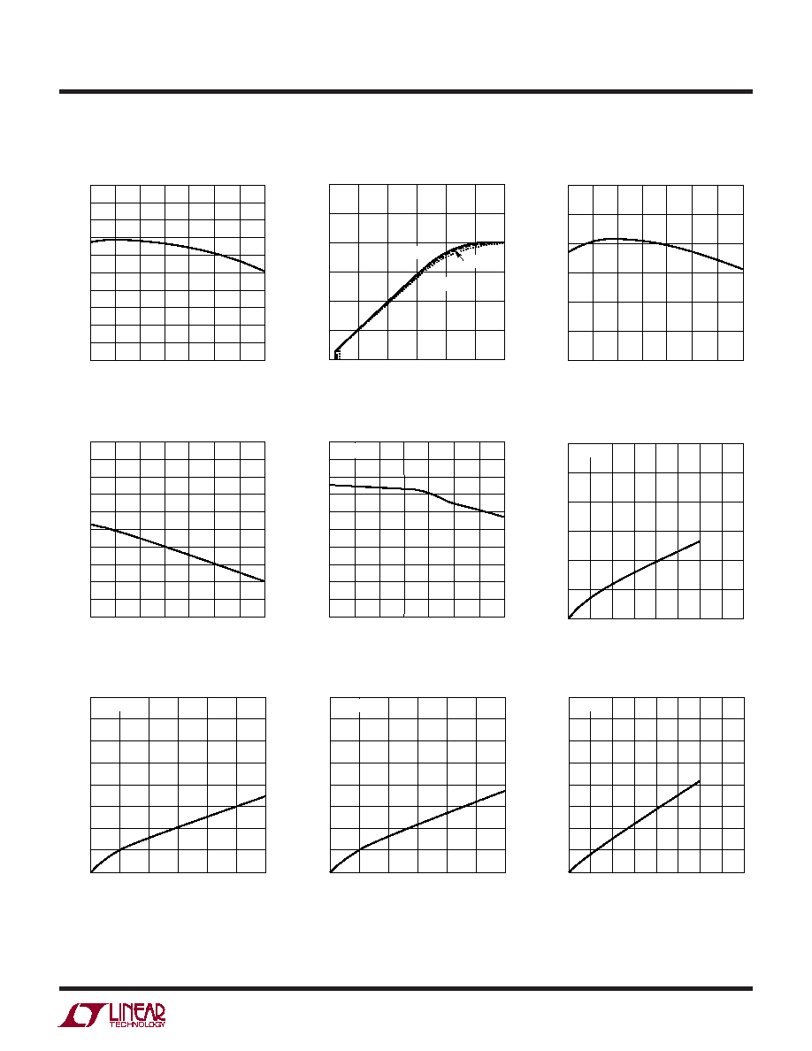
TYPICAL PERFOR A CE CHARACTERISTICS
U
W
V
FB1
Voltage
TEMPERATURE (
°C)
40
VOLTAGE (V)
1.26
1.27
1.28
20
60
1942 G01
1.25
1.24
20
0
40
80
100
1.23
1.22
TEMPERATURE (
°C)
40
155
VOLTAGE (mV)
154
152
151
150
145
148
0
40
60
1942 G02
153
147
146
149
20
20
80
100
TEMPERATURE (
°C)
40
VOLTAGE (V)
1.26
1.27
1.28
20
60
1942 G01
1.25
1.24
20
0
40
80
100
1.23
1.22
NFB2 Voltage
V
FB3
Voltage
LT1942
5
1942fa
TYPICAL PERFOR A CE CHARACTERISTICS
U
W
FB4 Voltage
V
FB4
vs CTRL4
Oscillator Frequency
TEMPERATURE (
°C)
40
190
V
FB4
(mV)
192
196
198
200
210
204
0
40
60
1942 G04
194
206
208
202
20
20
80
100
CTRL4 (V)
0
0
V
FB4
(mV)
50
100
150
200
300
0.5
1
1.5
2
1942 G05
2.5
3
250
T
A
= 40
°C
T
A
= 85
°C
T
A
= 25
°C
TEMPERATURE (
°C)
40
OSCILLATOR FREQUENCY (kHz)
1000
1100
1200
20
60
1942 G06
900
800
20
0
40
80
100
700
600
Quiescent Current
CT Timer Delay Time
SW1 Saturation Voltage
TEMPERATURE (
°C)
40
5.0
QUIESCENT CURRENT (mA)
5.5
6.5
7.0
7.5
10.0
8.5
0
40
60
1942 G07
6.0
9.0
9.5
8.0
20
20
80
100
TEMPERATURE (
°C)
40
0
DELAY TIME (ms)
1
3
4
5
10
7
0
40
60
1942 G08
2
8
9
6
20
20
80
100
C
T
= 0.1
µF
SW1 CURRENT (mA)
0
0
SW1 SATURATION VOLTAGE (mV) 100
200
300
400
50
100
200
150 175
1942 G09
500
600
25
75
125
T
A
= 25
°C
SW3 Saturation Voltage
SW2 Saturation Voltage
SW4 Saturation Voltage
SW3 CURRENT (mA)
0
SW3 SATURATION VOLTAGE (mV)
150
200
250
30
50
1942 G10
100
50
0
10
20
40
300
350
400
60
T
A
= 25
°C
SW2 CURRENT (mA)
0
SW2 SATURATION VOLTAGE (mV)
150
200
250
30
50
1942 G10
100
50
0
10
20
40
300
350
400
60
T
A
= 25
°C
SW4 CURRENT (mA)
0
SW4 SATURATION VOLTAGE (mV)
300
400
500
300
700
1942 G12
200
100
0
100 200
500 600
400
600
700
800
800
T
A
= 25
°C