1
LT1034-1.2/LT1034-2.5
Micropower Dual
Reference
RELATED PARTS
PART NUMBER
DESCRIPTION
COMMENTS
LT1004
Low Cost Precision Band-Gap
Micropower, SO-8, Industrial Temperature Options
LT1019
Precision Series or Shunt Band-Gap
Low Dropout, Multiple Output Options
LT1236
Precision Series or Shunt Buried Zener
Low Noise, Low Power, Multiple Output Options
s
Guaranteed 20 ppm/
░
C Drift
(H Package and Z Package)
s
Guaranteed 40 ppm/
░
C Drift (SO-8 Package)
s
20
Á
A to 20mA Operation (1.2V)
s
Dynamic Impedance: 1
s
7V, 100
Á
A Reference
The LT
«
1034 is a micropower, precision 1.2V/2.5 refer-
ence combined with a 7V auxiliary reference. The 1.2V/2.5V
reference is a trimmed, thin-film, band-gap, voltage refer-
ence with 1% initial tolerance and guaranteed 20ppm/
░
C
temperature drift. Operating on only 20
Á
A, the LT1034
offers guaranteed drift, low temperature cycling hyster-
esis and good long-term stability. The low dynamic im-
pedance makes the LT1034 easy to use from unregulated
supplies. The 7V reference is a subsurface zener device for
less demanding applications.
The LT1034 reference can be used as a high performance
upgrade of the LM385 or LT1004, where guaranteed
temperature drift is desired.
FEATURES
DESCRIPTIO
N
U
, LTC and LT are registered trademarks of Linear Technology Corporation.
s
Portable Meters
s
Precision Regulators
s
Calibrators
APPLICATIO
N
S
U
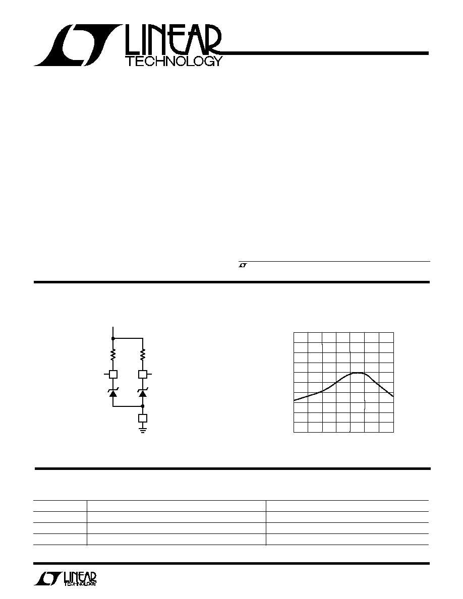
TYPICAL APPLICATIO
N
A
N
D BLOCK DIAGRA
M
U
U
W
Temperature Drift LT1034CS8-1.2
TEMPERATURE (
░
C)
ş50
REVERSE VOLTAGE CHANGE (mV)
2.5
2.0
1.5
1.0
0.5
0
ş0.5
ş1.0
ş1.5
ş2.0
ş2.5
0
50
75
LT1034 Ě TPC02
ş25
25
100
125
15V
7V OUTPUT
1.2V OR 2.5V
OUTPUT
50k
7V
500k
1.225V
OR 2.500V
LT1034 Ě TA01
2
LT1034-1.2/LT1034-2.5
Operating Current ................................................. 20mA
Forward Current (Note 1)...................................... 20mA
Storage Temperature Range ................. ş 65
░
C to 150
░
C
Lead Temperature (Soldering, 10 sec).................. 300
░
C
ABSOLUTE
M
AXI
M
U
M
RATINGS
W
W
W
U
Operating Temperature
Commercial ............................................. 0
░
to 70
░
C
Industrial .......................................... ş 40
░
C to 85
░
C
Military ........................................... ş 55
░
C to 125
░
C
ORDER PART
NUMBER
LT1034CS8-1.2
LT1034CS8-2.5
LT1034IS8-1.2
LT1034IS8-2.5
BOTTOM VIEW
H PACKAGE
3-LEAD TO-46 METAL CAN
7V
1.2V
T
JMAX
= 150
░
C,
JA
= 440
░
C/ W,
JC
= 80
░
C/ W
1
2
3
4
8
7
6
5
TOP VIEW
2.5V
NC
2.5V
7V
NC
NC
NC
GND
S8 PACKAGE
8-LEAD PLASTIC SO
LT1034BCH-1.2
LT1034BCH-2.5
LT1034BMH-1.2
LT1034BMH-2.5
LT1034CH-1.2
LT1034CH-2.5
LT1034MH-1.2
LT1034MH-2.5
PACKAGE/ORDER I
N
FOR
M
ATIO
N
W
U
U
ORDER PART NUMBER
T
JMAX
= 175
░
C,
JA
= 150
░
C/ W
T
JMAX
= 100
░
C,
JA
= 160
░
C/ W
BOTTOM VIEW
Z PACKAGE
3-LEAD TO-92 PLASTIC
7V
1.2V
ORDER PART NUMBER
LT1034BCZ-1.2
LT1034BCZ-2.5
LT1034BIZ-1.2
LT1034BIZ-2.5
LT1034CZ-1.2
LT1034CZ-2.5
LT1034IZ-1.2
LT1034IZ-2.5
LT1034-1.2
LT1034-2.5
PARAMETER
CONDITIONS
MIN
TYP
MAX
MIN
TYP
MAX
UNITS
Reverse Breakdown Voltage
I
R
= 100
Á
A
1.210 1.225
1.240
2.46
2.5
2.54
V
q
1.205 1.225
1.245
2.43
2.5
2.57
V
Reverse Breakdown Change
Note 3
0.5
2.0
1.0
3.0
mV
with Current
q
1.0
4.0
1.5
6.0
mV
2mA
I
R
20mA
4.0
8.0
6.0
16.0
mV
q
6.0
15.0
10.0
20.0
mV
Minimum Operating Current
q
10
20
15
30
Á
A
Temperature Coefficient
I
R
= 100
Á
A
LT1034B
q
10
20
10
20
ppm/
░
C
LT1034
20
40
20
40
ppm/
░
C
Reverse Dynamic Impedance (Note 2)
I
R
= 100
Á
A
0.25
1.0
0.5
1.5
q
0.50
2.0
1.0
2.5
Low Frequency Noise
I
R
= 100
Á
A, 0.1Hz
F
10Hz
q
4
6
Á
V
P-P
Long-Term Stability
I
R
= 100
Á
A
20
20
ppm
khrs
ELECTRICAL CHARACTERISTICS
T
A
= 25
░
C, unless otherwise specified.
PART MARKING
3401
3402
34I01
34I02
3
LT1034-1.2/LT1034-2.5
PARAMETER
CONDITIONS
MIN
TYP
MAX
UNITS
Reverse Breakdown Voltage
I
R
= 100
Á
A
6.80
7.0
7.3
V
q
6.75
7.0
7.4
V
Reverse Breakdown Change
100
Á
A
I
R
1mA
90
140
mV
with Current
100
Á
A
I
R
1mA
q
100
190
mV
1mA
I
R
20mA
160
250
mV
1mA
I
R
20mA
q
200
350
mV
Temperature Coefficient
I
R
= 100
Á
A
q
40
ppm/
░
C
Long-Term Stability
I
R
= 100
Á
A
20
ppm
khrs
7V Reference. T
A
= 25
░
C, unless otherwise specified.
ELECTRICAL CHARACTERISTICS
The
q
denotes specifications which apply over the full operating
temperature range.
Note 1: Forward biasing either diode will affect the operation of the other
diode.
Note 2: This parameter guaranteed by "reverse breakdown change with
current" test.
Note 3: For the LT1034-1.2: 20
Á
A
I
R
2mA. For the LT1034-2.5:
30
Á
A
I
R
2mA.
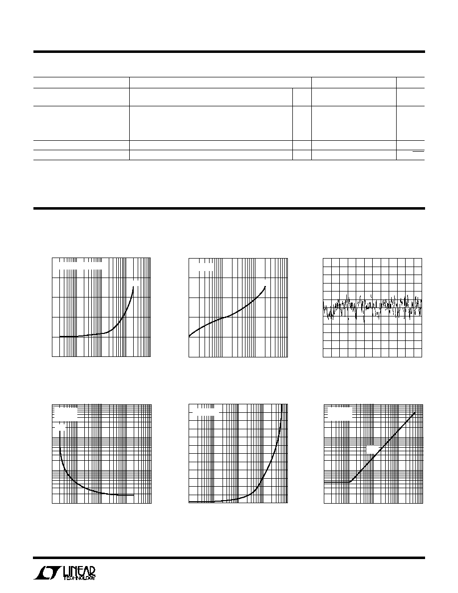
TYPICAL PERFOR
M
A
N
CE CHARACTERISTICS
U
W
0.1Hz to 10Hz Noise 1.2V
Reverse Voltage Change 7V
Reverse Voltage Change 1.2V
REVERSE CURRENT (mA)
0
REVERSE VOLTAGE CHANGE (mV)
2
4
6
8
0.01
1
10
100
LT1034 Ě TPC01
ş2
0.1
T
A
= ş55
░
C TO 125
░
C
1.2V
REVERSE CURRENT (mA)
0.1
ş0.1
REVERSE VOLTAGE CHANGE(V)
0.2
0.3
0.4
1
10
100
LT1034 Ě TPC02
0.1
0
T
A
= 25
░
C
7V
1s/DIV
0
ş11
2
Á
V/DIV
ş8
ş4
0
4
11
2
4
6
8
LT1034 Ě TPC03
10
12
1
3
5
7
9
11
8
ş10
ş6
ş2
2
10
6
Reverse Dynamic Impedance 7V
Reverse Dynamic Impedance 2.5V
Reverse Dynamic Impedance 1.2V
FREQUENCY (kHz)
REVERSE DYNAMIC IMPEDANCE (
)
60
50
40
30
20
10
0
0.01
1
10
100
LT1034 Ě TPC05
0.1
I
Z
= 100
Á
A
REVERSE CURRENT (mA)
1
REVERSE DYNAMIC IMPEDANCE (
)
10
0.01
1
10
100
LT1034 Ě TPC04
0.1
0.1
100
1.2V
T
A
= 25
░
C
f = 25Hz
FREQUENCY (Hz)
1
REVERSE DYNAMIC IMPEDANCE (
)
10
10
1k
10k
100k
LT1034 Ě TPC06
0.1
100
100
T
A
= 25
░
C
I
Z
= 100
Á
A
1.2V
Information furnished by Linear Technology Corporation is believed to be accurate and reliable.
However, no responsibility is assumed for its use. Linear Technology Corporation makes no represen-
tation that the interconnection of its circuits as described herein will not infringe on existing patent rights.

4
LT1034-1.2/LT1034-2.5
TYPICAL PERFOR
M
A
N
CE CHARACTERISTICS
U
W
REVERSE VOLTAGE (V)
0
REVERSE CURRENT (
Á
A)
8
12
1.6
LT1034 Ě TPC07
4
0
0.4
0.8
1.2
16
T
A
= ş55
░
C TO 125
░
C
V
REF
= 1.2V
REVERSE VOLTAGE (V)
0
REVERSE CURRENT (
Á
A)
100
80
60
40
20
0
8
LT1034 Ě TPC09
2
1
3
5
7
9
4
6
10
T
A
= ş55
░
C TO 125
░
C
V
REF
= 7V
REVERSE VOLTAGE (V)
REVERSE CURRENT (mA)
100
10
1
0.1
0.01
2.490
2.500
2.505
2.510
LT1034 Ě TPC02
2.495
Reverse Characteristics 7V
Reverse Characteristics 2.5V
Reverse Characteristics 1.2V
Response Time
Response Time
Forward Characteristics
FORWARD CURRENT (mA)
0.01
0
FORWARD VOLTAGE (V)
0.8
1.2
0.1
1
10
100
LT1034 Ě TPC10
0.4
T
A
= 25
░
C
TIME (
Á
s)
VOLTAGE (V)
8
6
4
2
0
15
0
60
LT1180A Ě TPC11
0
20
40
80
OUTPUT
INPUT
V
IN
V
OUT
82k
7V
TIME (
Á
s)
VOLTAGE (V)
1.5
1.0
0.5
0
5
0
300
LT1180A Ě TPC12
0
100
200
400
OUTPUT
INPUT
V
IN
V
OUT
36k
1.2V
PACKAGE DESCRIPTIO
N
U
Dimension in inches (millimeters) unless otherwise noted.
Linear Technology Corporation
1630 McCarthy Blvd., Milpitas, CA 95035-7417
(408) 432-1900
q
FAX
: (408) 434-0507
q
TELEX
: 499-3977
LT/GP 0995 2K REV D Ě PRINTED IN USA
ę
LINEAR TECHNOLOGY CORPORATION 1995
0.016 ş 0.019
(0.406 ş 0.483)
DIA
0.025
(0.635)
MAX
0.085 ş 0.105
(2.159 ş 2.667)
0.500
(12.700)
MIN
0.178 ş 0.195
(4.521 ş 4.953)
0.209 ş 0.219
(5.309 ş 5.537)
0.100
(2.540)
TYP
45
░
H3(46) 0594
0.050
(1.270)
TYP
0.050
(1.270)
TYP
0.028 ş 0.048
(0.711 ş 1.219)
0.036 ş 0.046
(0.914 ş 1.168)
0.015
(0.381)
MAX
FOR 3-LEAD PACKAGE ONLY
Z Package
Plastic
H Package
Metal Can
0.050
▒
0.005
(1.270
▒
0.127)
0.060
▒
0.005
(1.524
▒
0.127)
DIA
0.90
(2.286)
NOM
0.180
▒
0.005
(4.572
▒
0.127)
0.180
▒
0.005
(4.572
▒
0.127)
0.500
(12.70)
MIN
0.050
(1.270)
MAX
UNCONTROLLED
LEAD DIA
0.020
▒
0.003
(0.508
▒
0.076)
0.016
▒
0.03
(0.406
▒
0.076)
5
░
NOM
0.015
▒
0.02
(0.381
▒
0.051)
0.060
▒
0.010
(1.524
▒
0.254)
10
░
NOM
0.140
▒
0.010
(3.556
▒
0.127)
Z3 0694
1
2
3
4
0.150 ş 0.157*
(3.810 ş 3.988)
8
7
6
5
0.189 ş 0.197*
(4.801 ş 5.004)
0.228 ş 0.244
(5.791 ş 6.197)
0.016 ş 0.050
0.406 ş 1.270
0.010 ş 0.020
(0.254 ş 0.508)
Î
45
░
0
░
ş 8
░
TYP
0.008 ş 0.010
(0.203 ş 0.254)
SO8 0294
0.053 ş 0.069
(1.346 ş 1.752)
0.014 ş 0.019
(0.355 ş 0.483)
0.004 ş 0.010
(0.101 ş 0.254)
0.050
(1.270)
BSC
*THESE DIMENSIONS DO NOT INCLUDE MOLD FLASH OR PROTRUSIONS.
MOLD FLASH OR PROTRUSIONS SHALL NOT EXCEED 0.006 INCH (0.15mm).
S8 Package
8-Lead Plastic SO