
LND431LV
Low-voltage
Adjustable Precision Shunt Regulators
DATA SHEET
GENERAL DESCRIPTION
· Equivalent Full-Range Temperature
Coefficient 30ppm/şC
· Temperature Compensated for
Operation Over Full Rated Operating
Temperature Range
· Adjustable Output Voltage
· Sink Current Capability 1mA to 100mA
· Low
(0.2
Typ) Dynamic Output
Impedance
· Low
Output
Noise
FEATURES
The LND431LV are three-terminal low-voltage
adjustable shunt regulators with specified
thermal stability. The output voltage may be set
to any value between V
ref
(approximately 1.24V)
and 6V with two external resistors. These
devices have typical output impedance of 0.2
..
PIN CONFIGURATION
SYMBOL
· Linear Dimensions, Inc. · 445 East Ohio Street, Chicago IL 60611 USA · tel 312.321.1810 · fax 312.321.1830 ·
www.lineardimensions.com
·

PARAMETER
VALUE
UNITS
Cathode voltage (see note 1)
7
V
Continuous cathode current range
-20 to 20
Reference input current range
-.050 to 3.0
mA
Operating free-air temperature rage
0 to 70
Lead temperature 1.6mm from case for 10 seconds
260
şC
Note1: Voltage values are with respect to the anode terminal unless otherwise noted
PARAMETER
VALUE
MAX
UNITS
Cathode voltage, V
KA
V
ref
6
V
Cathode current, I
k
(for regulation)
.1
15
mA
ABSOLUTE MAXIMUM RATINGS
LND431LV
RECOMMENDED OPERATING CONDITIONS
· Linear Dimensions, Inc. · 445 East Ohio Street, Chicago IL 60611 USA · tel 312.321.1810 · fax 312.321.1830 ·
www.lineardimensions.com
·
FUNCTIONAL BLOCK DIAGRAM
+
CATHODE
-
REF
ANODE
V
REF
PARAMETER
SYMBOL
TEST
CIRCUIT
TEST CONDITIONS
MIN
TYP
MAX
UNIT
Reference input voltage
V
ref
1
V
KA =
V
ref
, I
k
=10mA
1222
1240
1258
Deviation of reference
input voltage over full
temperature range
V
ref(dev)
1
V
KA =
V
ref
, I
K
=10mA,
T
A =
Full range
4
12
mV
Ratio of change in
reference input voltage to
the change in cathode
voltage
V
ref
/
V
KA
2
I
K
=10
mA
V
KA
=6V to V
ref
-1.4
-2.7
mV/V
Reference input current
I
ref
2
I
K
=10mA, R1=10K
,
R2=
T
A
=full range
0.15
0.5
Deviation of reference
input current over full
temperature range
I
ref(dev)
2
I
K
=10mA, R1=10K
,
R2=
T
A
=full range
0.05
0.3
µA
Minimum cathode current
for regulation
I
min
1
V
KA =
V
ref
55
80
µA
Off- state cathode current
I
off
3
V
KA =
6 V, V
ref
= 0
0.001
1
µA
Dynamic impedance
|Z
KA
|
1
V
KA
=V
ref
, I
K
=1mA to
100mA, f
1KHz
0.2
0.4
Test Circuit 1. For V
KA
=V
REF
ELECTRICAL CHARACTERISTICS
LND431LV
PARAMETER MEASUREMENT INFORMATION
Test Circuit 2. For V
KA
> V
REF
· Linear Dimensions, Inc. · 445 East Ohio Street, Chicago IL 60611 USA · tel 312.321.1810 · fax 312.321.1830 ·
www.lineardimensions.com
·

Ref Input Current v/s Junction Temperature
Ref Voltage v/s Junction Temperature
LND431LV
PARAMETER MEASUREMENT INFORMATION
Test Circuit 3. For I
OFF
TYPICAL CHARACTERISTICS
Cathode Current v/s Cathode Voltage
KA
V
A
-10
K
10
V
Cathode Current (mA)
=
REF
V
T
I
Cathode Voltage (V)
-5
KA
0
5
15
25*C
=
1.5
0.5
-0.5
1
-1
0
=
T
V
Cathode Current (
REF
I
Cathode Voltage (V)
25*C
A
=
V
K
KA
V
KA
1
-1
-0.5
0
0.5
1.5
µ
A)
I
min
175
200
125
50
100
-50
25
75
150
-25
0
· Linear Dimensions, Inc. · 445 East Ohio Street, Chicago IL 60611 USA · tel 312.321.1810 · fax 312.321.1830 ·
www.lineardimensions.com
·
250
200
150
100
50
0
-50
-25
0
25
50
75
I
10 mA
K
=
T
J
- Junction Temperature - C
-
R
e
f
e
re
nc
e I
npu
t
C
u
r
r
ent
-
nA
I
RE
F
R1 = 10 k
R2 = Open
100
-
R
e
f
e
re
nc
e V
o
lt
ag
e
-
V
RE
F
V
T
10 mA
1.2360
J
1.2440
=
1.2340
K
25
-50
I
1.2420
-25
1.2400
- Junction Temperature - C
50
75
0
1.2380
100
L
C - Load Capacitance - F
0
0.2
0.4
0.6
0.8
1.0
C
a
t
hod
e C
u
rrent
- mA
0.001
0.01
0.1
1
10
µ
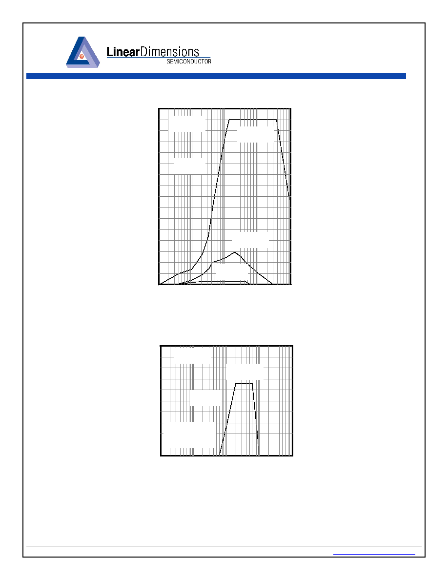
Tantalum Capacitors
* Stability boundary condition test shows that tantalum capacitors
are recommended to minimize the conditions that may cause
the device to oscillate.
LND431LV
· Linear Dimensions, Inc. · 445 East Ohio Street, Chicago IL 60611 USA · tel 312.321.1810 · fax 312.321.1830 ·
www.lineardimensions.com
·
L
C - Load Capacitance - F
0
2
4
6
8
10
12
14
16
C
a
t
h
o
de C
u
rren
t
- m
A
0.001
0.01
0.1
1
10
µ
Ceramic Capacitors
Stability Boundary Condition
T
A
=25
°C
V
KA
=Vref
Stable
V
KA
=2 V
V
KA
=3V
T
A
=25
°C
V
KA
=Vref
Stable
For V
KA
=2 & 3 V
Device does not
Oscillate