
Current Transducer LT 505-S
For the electronic measurement of currents : DC, AC, pulsed...,
with a galvanic isolation between the primary circuit (high power)
and the secondary circuit (electronic circuit).
Electrical data
I
PN
Primary nominal r.m.s. current
500
A
I
P
Primary current, measuring range
0 .. ± 1200
A
R
M
Measuring resistance @
T
A
= 70°C
T
A
= 85°C
R
M min
R
M max
R
M min
R
M max
with ± 15 V
@ ± 500 A
max
0
65
0
60
@ ± 800 A
max
0
15
0
12
with ± 24 V
@ ± 500 A
max
0
145
15 140
@ ± 1200 A
max
0
22
15
18
I
SN
Secondary nominal r.m.s. current
100
mA
K
N
Conversion ratio
1 : 5000
V
C
Supply voltage (± 5 %)
± 15 .. 24
V
I
C
Current consumption
30
(@ ± 24 V) +
I
S
mA
V
d
R.m.s. voltage for AC isolation test, 50 Hz, 1 mn
6
kV
V
b
R.m.s. rated voltage
1)
, safe separation
1750
V
basic isolation
3500
V
Accuracy - Dynamic performance data
X
G
Overall accuracy @ I
PN
, T
A
= 25°C
± 0.6
%
L
Linearity
< 0.1
%
Typ
Max
I
O
Offset current @ I
P
= 0, T
A
= 25°C
± 0.4
mA
I
OT
Thermal drift of I
O
- 10°C .. + 85°C
± 0.3 ± 0.5
mA
t
r
Response time
2)
@ 90 % of I
P max
< 1
µs
di/dt
di/dt accurately followed
> 50
A/µs
f
Frequency bandwidth (-
1
dB)
DC .. 150
kHz
General data
T
A
Ambient operating temperature
- 10 .. + 85
°C
T
S
Ambient storage temperature
- 25 .. + 100
°C
R
S
Secondary coil resistance @
T
A
= 70°C
65
T
A
= 85°C
69
m
Mass
400
g
Standards
3)
EN 50178
Notes :
1)
Pollution class 2. With a non insulated primary bar which fills the
through-hole
2)
With a di/dt of 100 A/µs
3)
A list of corresponding tests is available
Features
·
Closed loop (compensated) current
transducer using the Hall effect
·
Insulated plastic case recognized
according to UL 94-V0.
Advantages
·
Excellent accuracy
·
Very good linearity
·
Low temperature drift
·
Optimized response time
·
Wide frequency bandwidth
·
No insertion losses
·
High immunity to external
interference
·
Current overload capability.
Applications
·
AC variable speed drives and servo
motor drives
·
Static converters for DC motor drives
·
Battery supplied applications
·
Uninterruptible Power Supplies
(UPS)
·
Switched Mode Power Supplies
(SMPS)
·
Power supplies for welding
applications.
I
PN
= 500
A
980708/6
LEM Components
w w w .lem.com
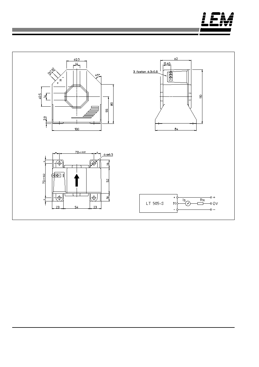
Secondary terminals
Terminal + : supply voltage + 15 .. 24 V
Terminal M : measure
Terminal - : supply voltage - 15 .. 24 V
Connection
Mechanical characteristics
·
General tolerance
± 0.5 mm
·
Fastening
4 holes
6.5 mm
·
Primary through-hole
40.5 x 40.5 mm
·
Connection of secondary
Faston 6.3 x 0.8 mm
Dimensions LT 505-S
(in mm. 1 mm = 0.0394 inch)
Front view
Top view
Left view
Remarks
·
I
S
is positive when I
P
flows in the direction of the arrow.
·
Temperature of the primary conductor should not exceed
100°C.
·
Dynamic performances (di/dt and response time) are best
with a single bar completely filling the primary hole.
·
This is a standard model. For different versions (supply
voltages, turns ratios, unidirectional measurements...),
please contact us.
LEM reserves the right to carry out modifications on its transducers, in order to improve them, without previous notice.