Document Outline
- Table of Contents
- ispLSI 8840 Data Sheet
- DC Electrical Characteristics
- AC Characteristics
- Signal Configuration: 432 BGA
- Ordering Information
ispLSI
®
8840
In-System Programmable
SuperBIGTM High Density PLD
8840_07
1
Copyright © 2000 Lattice Semiconductor Corp. All brand or product names are trademarks or registered trademarks of their respective holders. The specifications and information herein are subject
to change without notice.
LATTICE SEMICONDUCTOR CORP., 5555 Northeast Moore Ct., Hillsboro, Oregon 97124, U.S.A.
Tel. (503) 268-8000; 1-800-LATTICE; FAX (503) 268-8556; http://www.latticesemi.com
Features
· SuperBIG HIGH DENSITY IN-SYSTEM
PROGRAMMABLE LOGIC
-- 5V Power Supply
-- 45,000 PLD Gates/840 Macrocells
-- Up to 312 I/O Pins Supporting 3.3V/5V I/O
-- 1152 Registers
-- High-Speed Global and Big Fast Megablock (BFM)
Interconnect
-- Wide 20-Macrocell Generic Logic Block (GLB) for
High Performance
-- Wide Input Gating (44 Inputs per GLB) for Fast
Counters, State Machines, Address Decoders, Etc.
-- PCB-Efficient Ball Grid Array (BGA) Package
Options
· HIGH-PERFORMANCE E
2
CMOS
®
TECHNOLOGY
--
f
max = 110 MHz Maximum Operating Frequency
--
t
pd = 8.5 ns Propagation Delay
-- TTL Compatible Inputs and 3.3V/5V Outputs
-- PCI Compatible Inputs, Outputs and Speed Grades
-- Electrically Erasable and Reprogrammable
-- Non-Volatile
-- Programmable Speed/Power Logic Path
Optimization
· IN-SYSTEM PROGRAMMABLE
-- Increased Manufacturing Yields, Reduced Time-to-
Market and Improved Product Quality
-- Reprogram Soldered Devices for Faster Debugging
· 100% IEEE 1149.1 BOUNDARY SCAN TESTABLE AND
5V IN-SYSTEM PROGRAMMABLE
· ARCHITECTURE FEATURES
-- Enhanced Pin-Locking Architecture, Symmetrical
Generic Logic Blocks Connected by Hierarchical
Big Fast Megablock and Global Routing Planes
-- Product Term Sharing Array Supports up to 28
Product Terms per Macrocell Output
-- Macrocells Support Concurrent Combinatorial and
Registered Functions
-- Embedded Tristate Bus Can Be Used as an Internal
Tristate Bus or as an Extension of an External
Tristate Bus
-- Macrocell and I/O Registers Feature Multiple Control
Options, Including Set, Reset and Clock Enable
-- I/O Pins Support Programmable Bus Hold, Pull-Up,
Open-Drain and Slew Rate Options
-- Separate VCCIO Power Supply for Output Drivers
Supports 5V or 3.3V Outputs
-- I/O Cell Register Programmable as Input Register for
Fast Setup Time or Output Register for Fast Clock to
Output Time
· ispDesignEXPERTTM LOGIC COMPILER AND COM-
PLETE ISP DEVICE DESIGN SYSTEMS FROM HDL
SYNTHESIS THROUGH IN-SYSTEM PROGRAMMING
-- Superior Quality of Results
-- Tightly Integrated with Leading CAE Vendor Tools
-- Productivity Enhancing Timing Analyzer, Explore
Tools, Timing Simulator and ispANALYZERTM
-- PC and UNIX Platforms
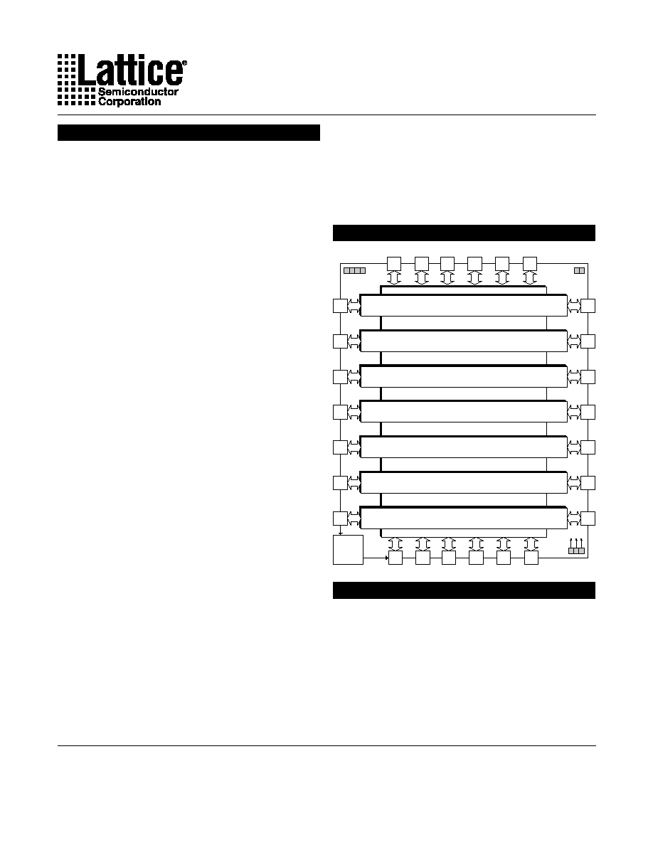
Functional Block Diagram
ispLSI 8000 Family Description
The ispLSI 8000 Family of Register-Intensive, SuperBIG
In-System Programmable Logic Devices is based on Big
Fast Megablocks of 120 registered macrocells and a
Global Routing Plane (GRP) structure interconnecting
the Big Fast Megablocks. Each Big Fast Megablock
contains 120 registered macrocells arranged in six groups
of 20, a group of 20 being referred to as a Generic Logic
Block, or GLB. Within the Big Fast Megablock, a Big Fast
Megablock Routing Pool (BRP) interconnects the six
GLBs to each other and to 24 Big Fast Megablock I/O
Global Routing Plane
12
I/O
12
I/O
Big Fast Megablock 0
12
I/O
12
I/O
Big Fast Megablock 1
12
I/O
12
I/O
Big Fast Megablock 3
12
I/O
12
I/O
Big Fast Megablock 4
12
I/O
12
I/O
Big Fast Megablock 6
12
I/O
12
I/O
Big Fast Megablock 5
12
I/O
12
I/O
Big Fast Megablock 2
12
I/O
12
I/O
12
I/O
12
I/O
12
I/O
12
I/O
12
I/O
12
I/O
12
I/O
12
I/O
12
I/O
12
I/O
Boundary
Scan
8840 block
January 2000
Specifications
ispLSI 8840
2
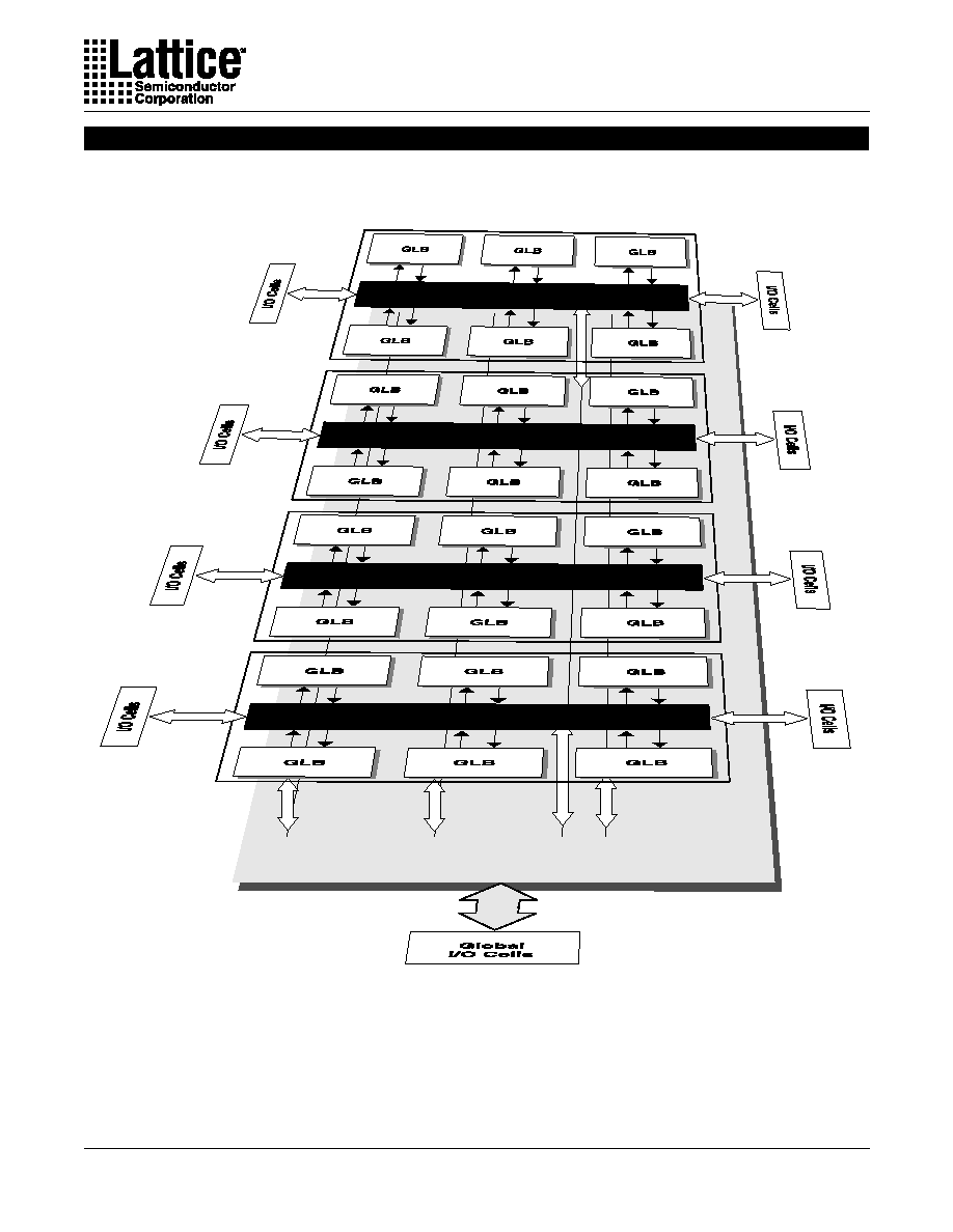
Figure 1. ispLSI 8840 Functional Block Diagram (Perspective)
Global Routing Plane (GRP) with Tristate Bus Lines
Big Fast Megablock Routing Pool (BRP)
Big Fast Megablock Routing Pool (BRP)
Big Fast Megablock Routing Pool (BRP)
Big Fast Megablock Routing Pool (BRP)
Functional Block Diagram
Specifications
ispLSI 8840
3
cells with optional I/O registers. The Global Routing
Plane which interconnects the Big Fast Megablocks has
an additional 144 global I/Os with optional I/O registers.
Outputs from the GLBs in a Big Fast Megablock can drive
both the Big Fast Megablock Routing Pool within the Big
Fast Megablock and the Global Routing Plane between
the Big Fast Megablocks. Switching resources are pro-
vided to allow signals in the Global Routing Plane to drive
any or all the Big Fast Megablocks in the device. This
mechanism allows fast, efficient connections, both within
the Big Fast Megablocks and between them.
Each GLB contains 20 macrocells and a fully populated,
programmable AND-array with 82 logic product terms.
The GLB has 44 inputs from the Big Fast Megablock
Routing Pool which are available in both true and comple-
ment form for every product term. Up to 20 of these inputs
can be switched to provide local feedback into the GLB
for logic functions that require it. The 80 general-purpose
product terms can be grouped into 20 sets of four and
sent into a Product Term Sharing Array (PTSA) which
allows sharing up to a maximum of 28 product terms for
a single function. Alternatively, the PTSA can be by-
passed for functions of four product terms or less.
The 20 registered macrocells in the GLB are driven by the
20 outputs from the PTSA or the PTSA bypass. Each
macrocell contains a programmable XOR gate, a pro-
grammable register/latch/toggle flip-flop and the
necessary clocks and control logic to allow combinatorial
or registered operation. Each macrocell has two outputs,
one output can be fed back inside the GLB to the AND-
array, while the other output drives both the Big Fast
Megablock Routing Pool and the Global Routing Plane.
This dual output capability from the macrocell allows
efficient use of the hardware resources. One output can
be a registered function for example, while the other
output can be an unrelated combinatorial function.
Macrocell registers can be clocked from one of several
global, local or product term clocks available on the
device. A global, local and product term clock enable is
also provided, eliminating the need to gate the clock to
the macrocell registers. Reset and preset for the macrocell
register is provided from both global and product term
signals. The polarity of all of these control signals is
selectable on an individual macrocell basis. The macro-
cell register can be programmed to operate as a D-type
register, a D-type flow-through latch or a T-type flip flop.
The 20 outputs from the GLB can drive both the Big Fast
Megablock Routing Pool within the Big Fast Megablock
and the Global Routing Plane between the Big Fast
Megablocks. The Big Fast Megablock Routing Pool con-
tains general purpose tracks which interconnect the six
GLBs within the Big Fast Megablock and dedicated
tracks for the signals from the Big Fast Megablock I/O
cells. The Global Routing Plane contains general pur-
pose tracks that interconnect the Big Fast Megablocks
and also carry the signals from the I/Os connected to the
Global Routing Plane.
Control signals for the I/O cell registers are generated
using an extra product term within each GLB, or using
dedicated input pins. Each GLB has two extra product
terms beyond the 80 available for the macrocell logic.
The first additional product term is used as an optional
shared product term clock for all the macrocells within the
GLB. The second additional product term is then routed
to an I/O Control Bus using a separate routing structure
from the Big Fast Megablock Routing Pool and Global
Routing Plane. Use of a separate control bus routing
structure allows the I/O registers to have many control
signals with no impact on the interconnection of the GLBs
and Big Fast Megablocks. The I/O Control Bus is split into
four quadrants, each servicing the I/O cell control re-
quirements for one edge of the device. Signals in the
control bus can be independently selected by any or all
I/O cells to act as clock, clock enable, output enable,
reset or preset.
Each Big Fast Megablock has 24 I/O cells. The Global
Routing Pool has 144 I/O cells. Each I/O cell can be
configured as a combinatorial input, combinatorial out-
put, registered input, registered output or bidirectional
I/O. I/O cell registers can be clocked from one of several
global, local or product term clocks which are selected
from the I/O control bus. A global and product term clock
enable is also provided, eliminating the need for the user
to gate the clock to the I/O cell registers. Reset and preset
for the I/O cell register is provided from both global and
product term signals. The polarity of all of these control
signals is selectable on an individual I/O cell basis. The
I/O cell register can be programmed to operate as a D-
type register or a D-type latch.
Inputs and outputs are PCI compatible. The input thresh-
old is fixed at TTL levels. The output driver can source
4mA and sink 8mA. The output drivers have a separate
VCCIO power supply which is independent of the main
VCC supply for the device. This feature allows the output
drivers to run from either 5V or 3.3V while the device logic
is always powered from 5V. The output drivers also
provide individually programmable edge rates and open
ispLSI 8000 Family Description (Continued)

Specifications
ispLSI 8840
4
drain capability. A programmable pullup resistor is pro-
vided to tie off unused inputs and a programmable
bus-hold latch is available to hold tristate outputs in their
last valid state until the bus is driven again by another
device.
The ispLSI 8000 Family features 5V, non-volatile in-
system programmability for both the logic and the
interconnect structures, providing the means to develop
truly reconfigurable systems. Programming is achieved
through the industry standard IEEE 1149.1-compliant
Boundary Scan interface using either the JTAG protocol
or Lattice proprietary ISP protocol. Boundary Scan test is
also supported through the same interface.
An enhanced, multiple cell security scheme is provided
that prevents reading of the JEDEC programming file
when secured. After the device has been secured using
this mechanism, the only way to clear the security is to
execute a bulk-erase instruction.
ispLSI 8840 Description
The ispLSI 8840 device has seven Big Fast Megablocks
for a total of 7 x 120 = 840 macrocells.
Each Big Fast Megablock has a total of 24 I/O cells and
the Global Routing Plane has a total of 144 I/O cells. This
gives (7 x 24) + 144 = 312 I/Os.
The total registers in the device is the sum of macrocells
plus I/O cells, 840 + 312 = 1152 registers.
Embedded Tristate Bus
There is a 108-line embedded internal tristate bus as part
of the Global Routing Plane (GRP), enabling multiple
GLBs to drive the same tracks. This bus can be parti-
tioned into various bus widths such as twelve 9-line
buses, six 18-line buses or three 36-line buses. The
GLBs can dynamically share a subset of the Global
Routing Plane tracks. This feature eliminates the need to
convert tristate buses to wide multiplexers on the pro-
grammable device. Up to 18 macrocells per GLB can
participate in driving the embedded tristate bus. The
remaining two macrocells per GLB are used to generate
the internal tristate driver control signals on each data
byte (with parity). The embedded tristate bus can also be
configured as an extension of an external tristate bus
using the bidirectional capability of the I/O cells con-
nected to the Global Routing Plane. The Global Routing
Plane I/Os 0-8 and 15-23 from each group (I/OGx as
defined in the I/O Pin Location Table) can connect to the
internal tristate bus as well as the unidirectional/non-
tristate global routing channels. I/Os 9-14 connect only to
the global routing channel.
The embedded tristate bus has internal bus hold and
arbitration features in order to make the function more
"user friendly". The bus hold feature keeps the internal
bus at the previously driven logic state when the bus is
not driven to eliminate bus float. The bus arbitration is
performed on a "first come, first served" priority. In other
words, once a logic block drives the bus, other logic
blocks cannot drive the bus until the first releases the bus.
This arbitration feature prevents internal bus contention
when there is an overlap between two bus enable sig-
nals. Typically, it takes about 3ns to resolve one bus
signal coming off the bus to another bus signal driving the
bus. The arbitration feature combined with the predict-
ability of CPLD, makes the embedded tristate bus the
most practical for the real world bus implementations.
ispLSI 8000 Family Description (Continued)

Specifications
ispLSI 8840
5
0
PT 0
PT 1
PT 2
To Output Control MUX
PT 3
Macrocell 0
Macrocell 19
To Interconnect
To Interconnect
PT 8
PT 9
PT 10
PT 11
Macrocell 2
To Interconnect
20
PT 4
PT 5
PT 6
PT 7
Macrocell 1
To Interconnect
Feedback Inputs
0
1
2
19
43
PT 76
PT 77
PT 78
PT 79
PT 81
PT 80
PT 12
PT 13
PT 14
PT 15
Macrocell 3
To interconnect
3
PTSA Bypass
Single PT
PT Clock
PT Preset
PT Reset
From PTSA
Shared PT Clock
From Tristate
Bus Track
Bus Input
PTSA Bypass
Single PT
PT Clock
PT Preset
PT Reset
From PTSA
Shared PT Clock
From Tristate
Bus Track
Bus Input
PTSA Bypass
Single PT
PT Clock
PT Preset
PT Reset
From PTSA
Shared PT Clock
From Tristate
Bus Track
Bus Input
PTSA Bypass
Single PT
PT Clock
PT Preset
PT Reset
From PTSA
Shared PT Clock
From Tristate
Bus Track
Bus Input
PTSA Bypass
Single PT
PT Clock
PT Preset
PT Reset
From PTSA
Shared PT Clock
From Tristate Bus Track
Bus Input
General Purpose Big Fast Megablock Input Tracks
I/O Big Fast Megablock Input Tracks
AND Array Input
Routing
Fully Populated
AND Array
Product Term
Sharing Array
Function Selector (E
2
Cell Controlled)
Note: Macrocells 9 and 10 do not support Tristate Bus Feedback.
Figure 2. ispLSI 8000 GLB Overview