Infrared Emitting Diodes(GaAs)
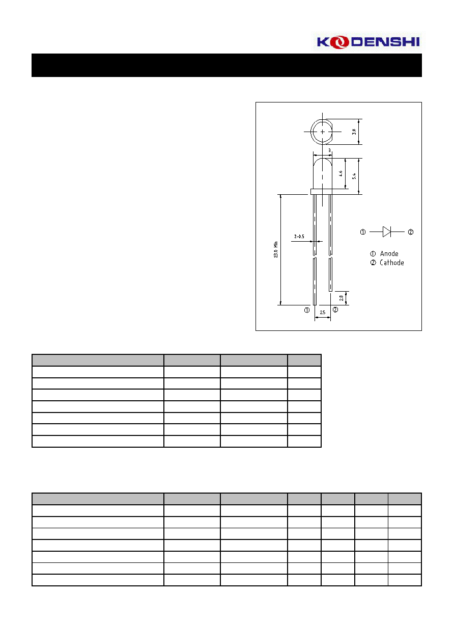
DIMENSIONS
(Unit : mm)
The KEL-3001A is GaAs infrared emitting diode that is designed
for high power, low forward voltage and high speed rise / fall time.
This device is optimized for speed and efficiency at emission
wavelength 940nm and has a high radient efficiency over a wide
range of forward current.
FEATURES
· 940nm wavelength
· Low forward voltage
· High power and high reliability
· Available for pulse operating
APPLICATIONS
· IR Audio and Telephone
· Communication
· Optical Switch
· Available for wireless digital data transmission
ABSOLUTE MAXIMUM RATINGS
(Ta=25°C)
Symbol
Unit
P
D
mW
I
F
mA
I
FP
A
V
R
V
Topr.
°C
Tstg.
°C
Tsol.
°C
*1. Duty ratio=1/100, pulse width=0.1ms
*2. Lead Soldering Temperature (3mm from case for 5sec).
ELECTRO-OPTICAL CHARACTERISTICS
(Ta=25°C)
Symbol
Min.
Typ.
Max.
Unit
V
F
-
1.4
1.7
V
I
R
-
-
10
uA
Ct
-
70
-
pF
Po
5.0
8.0
-
mW
p
-
940
-
nm
-
45
-
nm
-
± 20
-
deg.
KEL-3001A
I
F
=50mA
I
F
=50mA
Spectral bandwidth 50%
Half angle
240
Soldering temp. *2
Item
Conditions
Reverse current
Capacitance
V
R
=5V
f=1MHz, V=0V
Radiant intensity
I
F
=50mA
50
0.5
Forward current
Pulse forward current *1
-30 ~ +85
Storage temp.
Forward voltage
I
F
=50mA
Item
Ratings
Peak emission wavelength
I
F
=50mA
Reverse voltage
Operating temp.
5
-25 ~ +85
75
Power dissipation
Infrared Emitting Diodes(GaAs)
KEL-3001A
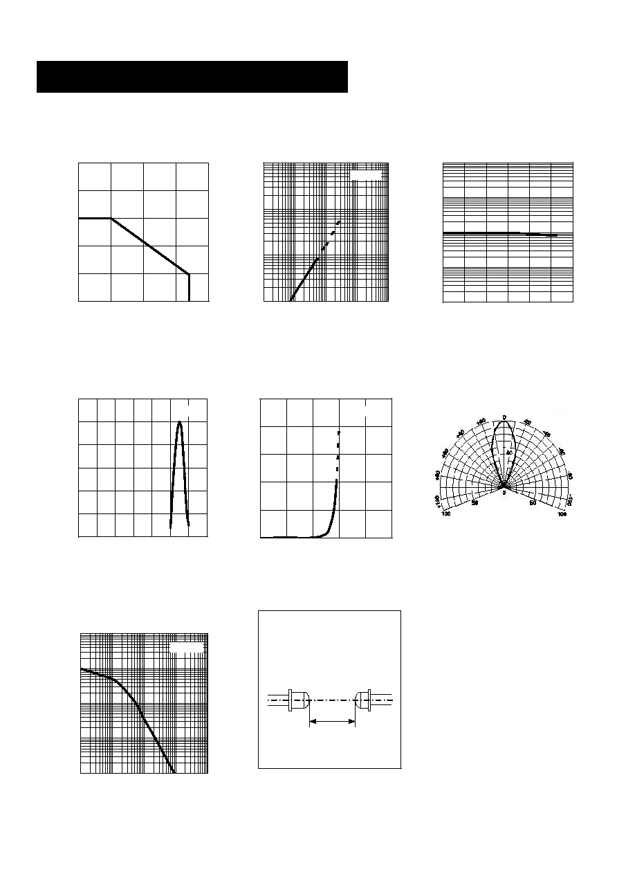
Power dissipation Vs.
Ambient temperature
0
25
50
75
100
125
0
25
50
75
100
Ambient temperature Ta [°C]
Power dissipation P
D
[mW]
Radiant intensity Vs.
Forward current
1
10
100
1000
1
10
100
1000
10000
Forward current I
F
[mA]
Radiant intensity Po [mW]
Relative radiant intensity Vs.
Ambient temperature
0.01
0.1
1
10
100
-20
0
20
40
60
80
100
Ambient temperature Ta [°C]
Relative radiant intensity Po
Relative intensity Vs.
Wavelength
0
20
40
60
80
100
120
400
500
600
700
800
900
1000 1100
Wavelength
[nm]
Relative intensity [%]
Forward current Vs.
Forward voltage
0
25
50
75
100
125
0
0.5
1
1.5
2
2.5
Forward voltage V
F
[V]
Forward current I
F
[mA]
Relative radiant intensity Vs.
Distance
0.1
1
10
100
1000
0.1
1
10
100
1000
Distance l [mA]
Relative radiant intensity Po [%]
Relative radiant intensity Vs.
Distance test method
Ta=25°C
Ta=25°C
Ta=25°C
Ta=25°C
Ta=25°C
Radiant Pattern
Angle (deg.)
Relative intensity (%)
I
F
=50mA
Detector
l